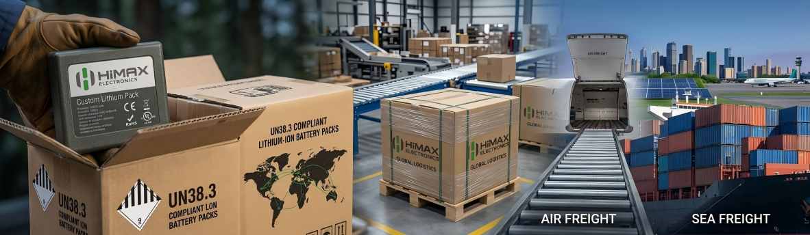
As the demand for lithium batteries continues to grow around the world, more battery systems are being used in electric vehicles, RVs, marine equipment, solar energy storage systems, telecommunications, and other outdoor applications. Many of these applications must operate throughout the winter, where temperatures can remain below freezing for long periods. Under these conditions, one important question often arises: How can LiFePO₄ batteries be charged safely in cold weather?
At HIMAX ELECTRONICS, we frequently receive questions from customers about battery charging performance in low-temperature environments. While LiFePO₄ batteries offer excellent safety, long cycle life, and stable performance, they should not be charged below 0°C without proper protection. Charging at freezing temperatures can permanently damage the battery cells and shorten their service life.
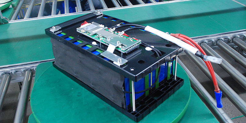
To solve this challenge, the battery industry has developed a reliable and proven solution: low-temperature heating technology. By combining intelligent Battery Management System (BMS) control with heating pads installed inside the battery pack, batteries can be safely warmed before charging begins. This technology has become one of the most practical and widely adopted methods for protecting LiFePO₄ batteries in cold climates.
In this article, HIMAX ELECTRONICS explains how low-temperature heating technology works, why it is necessary, and which solution is the most suitable for different applications.
Why Is Charging a LiFePO₄ Battery Below 0°C Dangerous?
Many users believe that if a battery can discharge at low temperatures, it should also be able to charge normally. In reality, charging and discharging are very different.
A LiFePO₄ battery can continue to discharge at temperatures below freezing, although its available capacity will decrease. Charging, however, is much more sensitive to temperature.
When a LiFePO₄ battery is charged below 0°C, lithium ions cannot move normally inside the battery cell. Instead of being absorbed into the anode material, some lithium deposits on the surface of the anode. This phenomenon is called lithium plating.
Lithium plating causes several serious problems:
- Permanent capacity loss
- Higher internal resistance
- Reduced cycle life
- Lower charging efficiency
- Increased safety risks in severe cases
Unlike temporary performance loss caused by cold weather, lithium plating is irreversible. Once it occurs, the battery cannot recover to its original condition.
For this reason, most LiFePO₄ battery manufacturers recommend not charging batteries below 0°C unless an effective heating system is installed.
How Does the Low-Temperature Heating System Work?
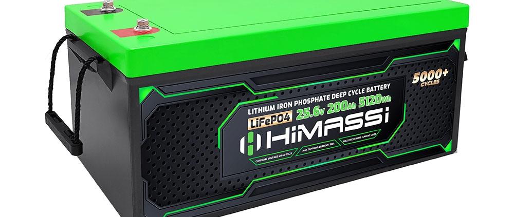
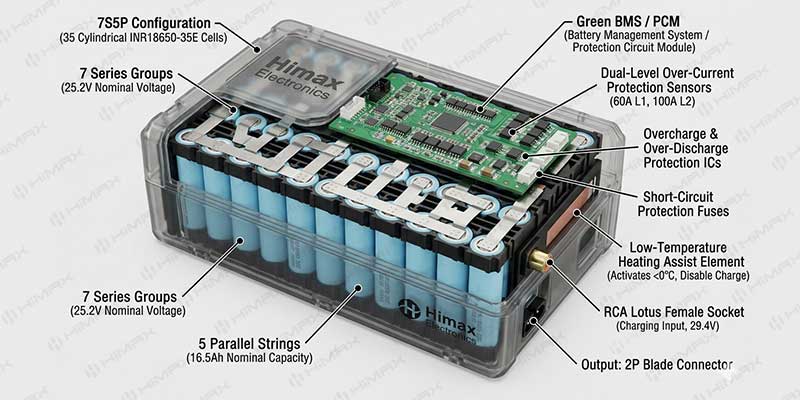
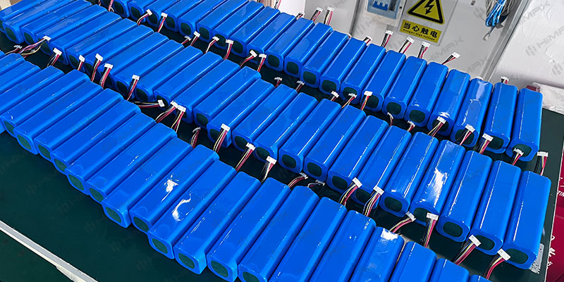
The most common solution used today is to install a heating pad inside the battery pack.
The heating pad is attached directly to the battery cells to ensure efficient heat transfer. It works together with the Battery Management System (BMS) to automatically protect the battery during charging.
The charging process is simple and fully automatic.
Step 1 – Temperature Monitoring
The BMS continuously monitors the battery cell temperature using built-in NTC temperature sensors.
These sensors provide real-time temperature information to the BMS throughout battery operation.
Step 2 – Heating Starts
If the battery temperature drops below 0°C, the BMS does not allow charging to begin immediately.
Instead, it activates the heating pad.
At this stage, the charger supplies power only to the heating pad rather than charging the battery cells.
Step 3 – Battery Temperature Rises
The heating pad gradually warms the battery cells through direct thermal contact.
This method is much more efficient than heating the entire battery compartment because the heat is transferred directly where it is needed.
Step 4 – Safe Charging Begins
Once the battery cell temperature reaches approximately 10°C, the BMS automatically turns off the heating pad.
The charging process then starts normally.
The temperature threshold can be adjusted according to customer requirements or specific applications.
This intelligent control ensures that charging only occurs when the battery is within a safe operating temperature range.
Why Is This Solution So Popular?
Low-temperature heating technology has become the preferred solution because it offers several important advantages.
Improved Battery Safety
The heating system prevents charging below freezing temperatures, protecting the battery from irreversible damage.
Fully Automatic Operation
Users do not need to manually switch the heater on or off.
Everything is controlled automatically by the BMS.
Better Battery Life
Because the battery is only charged within the recommended temperature range, its cycle life can be significantly extended.
High Reliability
This technology has already been widely adopted in many applications, including:
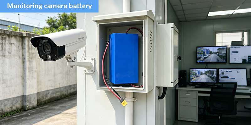
- Residential energy storage systems
- Solar energy storage
- RV batteries
- Marine batteries
- Off-grid power systems
- Telecommunications backup batteries
- Industrial equipment
It is considered one of the most mature and reliable low-temperature charging solutions available today.
Should the Battery Be Heated During Discharge?
Some customers ask whether the battery should also be heated while discharging.
Our engineering team generally does not recommend this design.
During discharge, the battery itself is supplying power to the external equipment.
If the heating pad is activated at the same time, it consumes energy directly from the battery.
This means:
- Less available battery capacity
- Shorter operating time
- Lower system efficiency
For most standard energy storage applications, the disadvantages outweigh the benefits.
Therefore, discharge heating is rarely used in the battery industry.
Instead, the heating function is normally used only before charging.
Is Thermal Insulation a Good Solution?
Another common question is whether thermal insulation materials should be added around the battery pack.
Although insulation can help retain some heat during winter, HIMAX ELECTRONICS generally does not recommend this approach.
The main reason is that insulation works in both directions.
During cold weather, it slows heat loss.
However, during summer or high-load operation, it also slows heat dissipation.
As a result, excessive heat may accumulate inside the battery pack.
High temperatures can also shorten battery life and reduce long-term reliability.
A properly controlled heating system is therefore a much better solution than simply adding insulation materials.
What If the Application Requires Better Low-Temperature Discharge Performance?
The heating pad solution mainly protects charging.
However, some applications also require excellent discharge performance in extremely cold environments.
For these applications, low-temperature LiFePO₄ cells may be a better choice.
The difference between standard cells and low-temperature cells is significant.
A standard LiFePO₄ cell typically delivers only about 40% of its rated capacity at -20°C.
A specially designed low-temperature LiFePO₄ cell can deliver approximately 70% to 80% of its rated capacity at -20°C.
This greatly improves system performance in freezing environments.
However, customers should also consider the following:
- Low-temperature cells are more expensive.
- Custom development may be required.
- Minimum order quantities are usually much higher than standard products.
For projects that only require safe winter charging, the heating pad solution is usually the more economical choice.
For projects that require high discharge capacity at extremely low temperatures, customized low-temperature cells may provide better overall performance.
Are There Self-Heating Battery Cells?
This is another question we receive regularly.
At present, there are no commercially available LiFePO₄ battery cells with built-in self-heating capability.
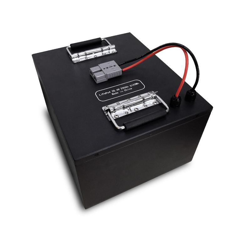
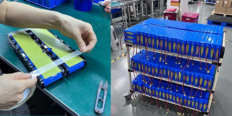
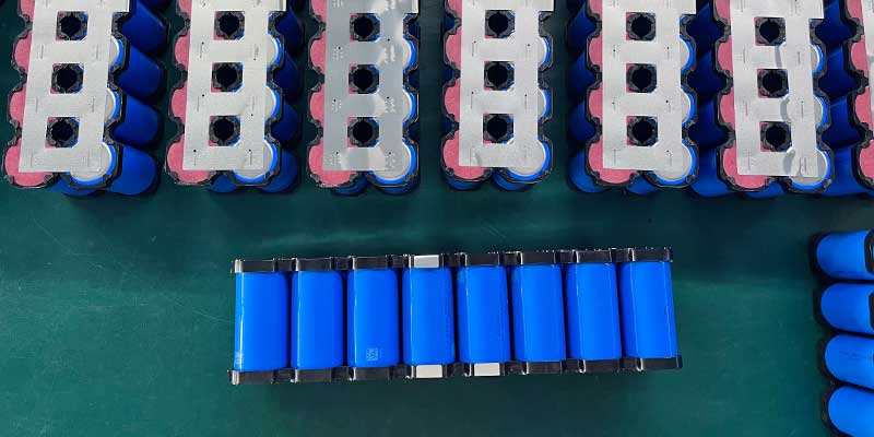
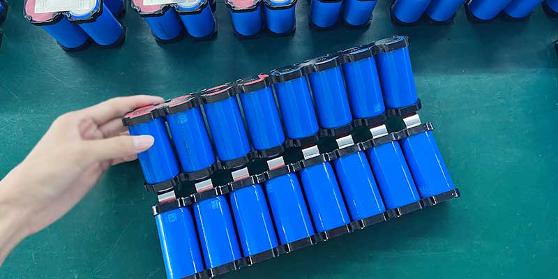
Instead, the heating function is achieved at the battery pack level.
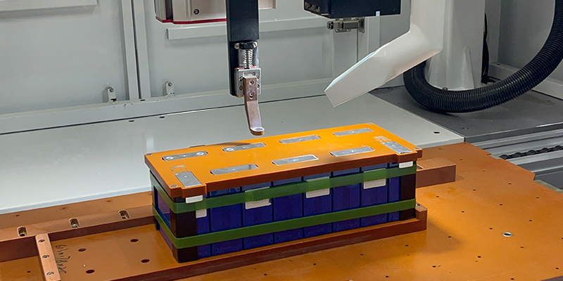
A complete heating system includes:
- Heating pads
- NTC temperature sensors
- Battery Management System (BMS)
- Intelligent heating control logic
These components work together to provide safe and reliable low-temperature charging.
HIMAX ELECTRONICS’ Experience in Low-Temperature Battery Design
At HIMAX ELECTRONICS, we have successfully developed customized battery packs with integrated low-temperature heating systems for customers in different industries.
Our engineering team designs the heating system according to the customer’s battery specifications, operating temperature, charging requirements, and application environment.
Every project is carefully evaluated to ensure safe operation, reliable performance, and long service life.
Whether the battery is used in renewable energy systems, industrial equipment, RVs, marine applications, or other outdoor environments, we can recommend the most suitable low-temperature solution.
Conclusion
Cold weather should never prevent your battery system from operating safely and reliably.
By combining intelligent BMS control with heating pads, low-temperature heating technology effectively prevents battery damage caused by charging below freezing temperatures. It is a mature, safe, and cost-effective solution that has been widely adopted across the battery industry. For applications requiring better discharge performance in extreme cold, customized low-temperature LiFePO₄ cells provide another reliable option.
At HIMAX ELECTRONICS, we are committed to providing customized lithium battery solutions that meet the requirements of real-world applications. Whether you need a battery pack with an integrated low-temperature heating system or a solution using specialized low-temperature cells, our experienced engineering team is ready to help.
If you would like to learn more about our customized LiFePO₄ battery solutions, please contact HIMAX ELECTRONICS. We look forward to helping you build reliable energy storage systems that perform safely and efficiently throughout every season.