Battery Pack Design Best Practices: Cell Configuration, BMS Integration, and Thermal Management
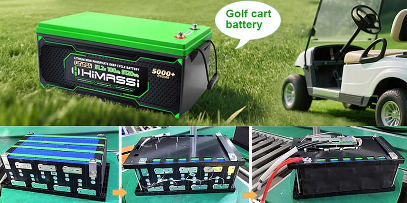
Designing a battery pack is an exercise in balancing competing constraints: energy density against safety, cost against longevity, and manufacturability against performance. Whether the application is an electric vehicle, a stationary energy storage system, or a portable device, three pillars determine whether a pack will perform reliably over its intended lifetime — cell configuration, battery management system (BMS) integration, and thermal management. This article walks through the design considerations and best practices in each of these areas.
1. Cell Configuration
Choosing the Right Cell Format
Lithium-ion cells come in three dominant form factors, each with tradeoffs:
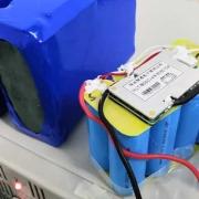
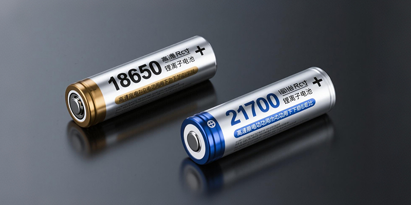
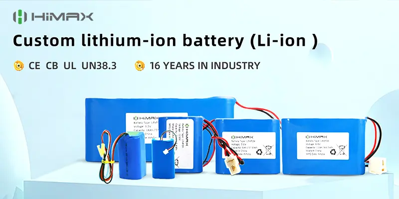
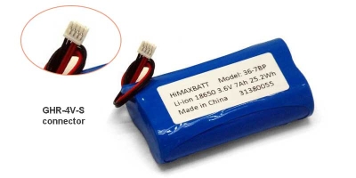
- Cylindrical cells(e.g., 18650, 21700, 4680) offer mature manufacturing, consistent quality control, and good mechanical robustness. Their round shape does leave some unused volume in a pack, and thermal management requires managing many small heat sources rather than a few large ones.
- Prismatic cellspack more efficiently into rectangular enclosures and simplify module-level thermal design, but tooling costs are higher and swelling over the cell’s life must be accommodated mechanically.
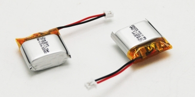
- Pouch cellsoffer the highest packaging efficiency and flexibility in form factor, but they are the most mechanically vulnerable and require external compression and support structures to manage swelling and maintain cell-to-cell contact.
The choice should be driven by the application’s volumetric constraints, expected production volume, and how much engineering effort can go into custom mechanical support.

Series and Parallel Arrangement
Pack voltage is set by the number of cells in series (S), and pack capacity/current capability is set by the number of parallel strings (P), commonly written as an “SxP” configuration (e.g., 14s4p).
Best practices include:
- Match cells within a parallel group tightly.Cells grouped in parallel should be binned by capacity and internal resistance (typically within 1-2%) before assembly. Mismatched cells in a parallel group will experience circulating currents, with the lower-resistance cell absorbing a disproportionate share of load — accelerating its degradation and creating a self-reinforcing imbalance.
- Consider parallel-then-series (P-then-S) vs series-then-parallel (S-then-P) topology carefully.In P-then-S designs, cells are grouped in parallel first, which helps average out cell-level variation within each group but means a single cell fault can be harder to isolate without taking down the whole parallel block. S-then-P designs (series strings connected in parallel) allow better fault isolation per string but can create larger circulating currents between strings if strings are not perfectly matched。
- Fuse or otherwise protect parallel groups individually where practical, so that an internal short in one cell doesn’t discharge the entire parallel group’s energy into the fault, which is a significant thermal event risk.
- Account for interconnect resistance.Busbars and welds add resistance that, if uneven across parallel paths, will cause current imbalance even with well-matched cells. Symmetric busbar layouts and consistent weld quality (monitored via pull-testing or resistance testing at production) matter as much as cell selection.
- Leave margin for capacity fade.Since cells degrade over life, design the S-count for the end-of-life voltage window, not just the beginning-of-life window, so the pack still meets minimum voltage requirements after years of service.
Mechanical and Structural Considerations
- Cylindrical and prismatic cells need spacers or a rigid frame to control cell-to-cell spacing for both thermal and vibration reasons.
- Pouch cells require compression fixtures (typically 1-3% of cell thickness compression) to manage swelling, prevent delamination-induced capacity fade, and keep internal contact pressure uniform.
- Crash and vibration requirements (especially in automotive and aerospace applications) dictate enclosure stiffness, cell retention strategy, and the need for crumple zones or venting paths that direct any thermal event away from occupants or critical systems.
2. BMS Integration
The BMS is the pack’s nervous system: it measures, protects, balances, and communicates. Poor BMS integration is one of the most common causes of premature pack failure or field safety incidents, even when cell-level design is sound.
Core BMS Functions
- Voltage monitoringat the cell or cell-group level, with sufficient sampling rate and accuracy (typically ±2-5 mV) to catch developing faults early.
- Current monitoringvia shunt or Hall-effect sensors, feeding both protection logic and state-of-charge (SOC) estimation.
- Temperature monitoringat multiple points per module — not just one sensor per pack — since thermal gradients within a pack can be significant.
- State estimation(SOC, state of health/SOH, state of power) using algorithms such as coulomb counting combined with periodic voltage-based recalibration, or more advanced Kalman-filter-based approaches for higher accuracy.
- Cell balancing, either passive (resistive bleed of higher-voltage cells) or active (charge redistribution between cells), to keep cells within a parallel or series group aligned over time.
- Protection functions: over-voltage, under-voltage, over-current, over-temperature, and short-circuit protection, typically implemented redundantly in both hardware (analog comparators) and firmware, so a software fault cannot disable protection entirely.
Best Practices for Integration
- Design for redundancy in safety-critical protections.Hardware-level over-voltage and over-current cutoffs should exist independently of the microcontroller’s software logic, so a firmware hang or bug cannot leave the pack unprotected.
- Distribute sense wiring carefully.Long, unshielded sense lines are susceptible to noise and can create ground-loop issues; twisted-pair wiring and common-mode filtering are standard mitigations.
- Isolate high-voltage and low-voltage domains.Galvanic isolation (optocouplers, isolated ADCs, or isolated CAN transceivers) between the battery’s high-voltage side and the low-voltage control/communication side protects both equipment and personnel.
- Choose a balancing strategy that matches the application.Passive balancing is cheaper and adequate for many consumer and stationary storage applications, but active balancing recovers more usable capacity and reduces heat generation in high-power applications like EVs, where imbalance can otherwise waste meaningful pack capacity over time.
- Plan for communication robustness.CAN bus, SMBus, or proprietary serial protocols used between BMS and the vehicle/system controller should include checksums, timeout handling, and clearly defined fault states so a communication dropout results in a safe default (e.g., contactors opening) rather than an undefined condition.
- Validate SOC/SOH algorithms against real usage profiles, not just steady-state lab discharge curves. SOC estimation error tends to grow under dynamic, high-current-ripple conditions typical of real-world EV or grid-storage duty cycles, so algorithms should be tuned and validated against representative field data.
- Include diagnostic and data-logging capability.Onboard logging of cell voltages, temperatures, and fault events dramatically simplifies field failure analysis and warranty investigations.
3. Thermal Management
Temperature is the single largest driver of both battery aging and safety risk. Cells generally degrade fastest above roughly 35-40°C and also underperform and lithium-plate when charged too cold (below 0°C), so thermal management has to address both heating and, in some climates, preheating.
Sources of Heat
- Ohmic (resistive) heating, proportional to I²R, which scales with current draw and increases as internal resistance rises with cell aging.
- Entropic heating/coolingfrom the electrochemical reaction itself, which can be exothermic or endothermic depending on the state of charge and direction of current.
- Ambient and environmental heat load, especially relevant for packs mounted near power electronics or exposed to direct sun.
Cooling Architecture Options
- Passive/conduction coolingusing thermal interface materials and metal enclosures or cold plates, suitable for lower-power applications where heat generation is modest and thermal mass alone can absorb transients.
- Forced air cooling, common in earlier-generation EVs and many consumer/stationary systems, offering simplicity and low cost but limited heat transfer coefficient and difficulty maintaining tight, uniform temperatures across a large pack.
- Liquid cooling(cold plates or immersion), now standard in most high-performance EV packs, offering much higher heat transfer capability and better temperature uniformity, at the cost of added complexity, weight, sealing requirements, and potential leak risk that must be engineered against.
- Immersion cooling, an emerging approach where cells sit directly in a dielectric fluid, offering excellent uniformity and even fire-suppression benefits, though it is less mature in mass production and raises material-compatibility and serviceability questions.
Best Practices
- Design for temperature uniformity, not just average temperature.A pack with a 5°C average temperature but a 15°C spread across cells will age unevenly, with the hottest cells degrading fastest and eventually driving pack-level capacity loss and imbalance. Uniformity is often more important than absolute minimum temperature.
- Co-design the cooling path with the cell/module layout early, not as an afterthought. Cold plate channel routing, coolant flow direction, and cell placement should be optimized together — for example, arranging the coolant inlet and outlet so that no single cell always sits at the “hot end” of the flow path.
- Size the thermal system for worst-case duty cycles, including fast charging and sustained high-power discharge (e.g., towing or track use in an EV), not just typical driving or usage patterns.
- Include thermal runaway propagation mitigation.Even with excellent thermal management, cell-level failures can occur from manufacturing defects or external damage. Best practice includes physical barriers or spacing between cells/modules, venting paths that direct hot gases away from occupants or adjacent modules, and materials (mica, ceramic-fiber barriers, intumescent coatings) designed to slow propagation and buy time for evacuation or fire suppression.
- Preheat in cold climates.For applications that must charge or operate in sub-zero conditions, integrate heating elements (resistive heaters or reversing the cooling loop as a heat pump) with charge-current limiting until cells reach a safe minimum temperature, to avoid lithium plating during cold charging.
- Validate with instrumented prototypes.Simulation (CFD, thermal network models) is essential for early design, but should be validated against physical prototypes instrumented with thermocouples at multiple pack locations under representative load profiles before finalizing the design.
- Coordinate thermal management with the BMS.Temperature sensor placement, cooling system control logic, and BMS-driven current derating should be designed together so the system can proactively reduce load before hitting protection thresholds, rather than relying on hard cutoffs as the primary control mechanism.
Bringing It Together
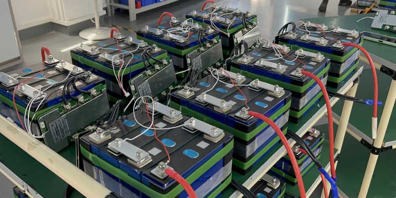
None of these three domains can be optimized in isolation. Cell configuration decisions affect how heat is generated and distributed; thermal management constrains how aggressively the BMS can allow charging or discharging; and BMS balancing strategy affects how evenly cells age within a given configuration. The most reliable, long-lived, and safe battery packs come from teams that treat cell selection, electrical architecture, control electronics, and thermal design as a single integrated system from the earliest concept stage — rather than sequential, siloed engineering handoffs.
A useful discipline is to define pack-level requirements (cycle life, calendar life, fast-charge capability, operating temperature range, safety certification targets) before locking in cell chemistry or format, and then to validate the interacting design choices — configuration, BMS, and thermal — against those requirements together, using both simulation and physical test data, before committing to production tooling.