Solar Street Light Battery Guide: 12V LiFePO4 Solutions
By Alden – Battery Engineer – Manufacturing & Quality Control
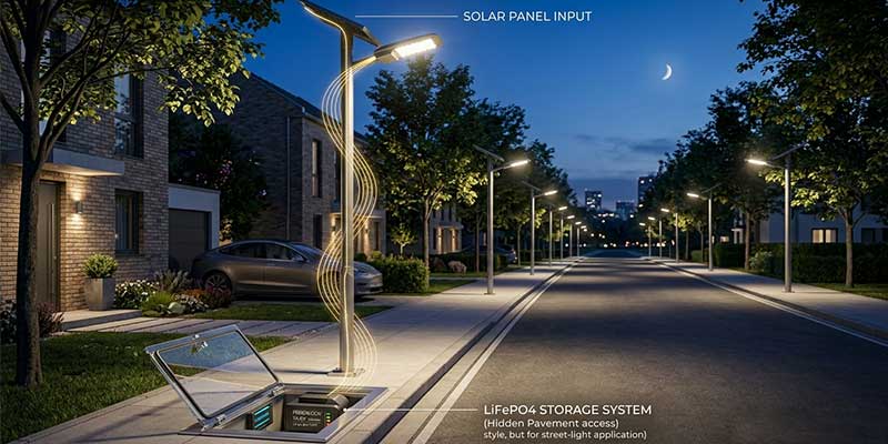
Solar street lights are expected to work every night, often in remote locations where maintenance is costly and inconvenient. While solar panels and LED fixtures receive most of the attention, the battery pack is the component that determines whether a solar street light can deliver reliable illumination through cloudy weather, seasonal changes, and years of outdoor operation.
At Himax Electronics, we recently supported solar street lighting projects using 12V 18Ah LiFePO4 battery packs and 12V 48Ah LiFePO4 battery packs. Although both batteries serve the same application, they address different runtime and power requirements.
This article explains how these battery packs are used in solar street lighting systems, what makes LiFePO4 technology suitable for outdoor lighting, and how OEM buyers can select the right battery solution.
Why Battery Selection Matters in Solar Street Lights
A solar street light operates as a complete energy system:
- Solar panel captures energy during the day.
- Charge controller manages charging.
- Battery stores energy.
- LED light consumes stored energy at night.
When the battery underperforms, the entire lighting system suffers. Common problems include:
- Reduced lighting hours
- Dim illumination before dawn
- Frequent battery replacement
- System downtime during cloudy periods
- Increased maintenance costs
For municipalities, contractors, and lighting equipment manufacturers, battery reliability directly impacts project success.
The Advantages of LiFePO4 Batteries for Solar Street Lights
Compared with traditional lead-acid batteries, LiFePO4 battery technology offers several important benefits.
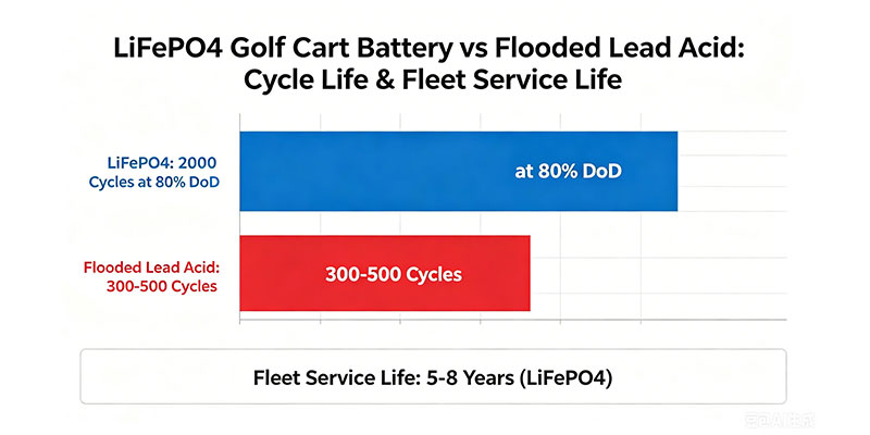
Longer Cycle Life
Solar street lights charge and discharge every day. This means the battery may experience hundreds of cycles annually.
LiFePO4 cells typically provide significantly longer cycle life than conventional lead-acid alternatives, helping reduce replacement frequency and long-term operating costs.
Improved Safety
Safety is critical for batteries installed in public areas.
LiFePO4 chemistry offers:
- Excellent thermal stability
- Reduced risk of thermal runaway
- Better tolerance to outdoor temperature variations
- Reliable long-term operation
Higher Energy Efficiency
A more efficient battery stores and delivers energy with lower losses.
This allows solar lighting systems to:
- Maximize harvested solar energy
- Extend nighttime runtime
- Improve overall system efficiency
Lightweight Construction
LiFePO4 batteries are lighter than comparable lead-acid batteries, making installation easier and reducing structural requirements.
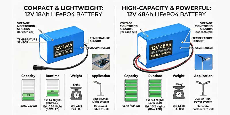
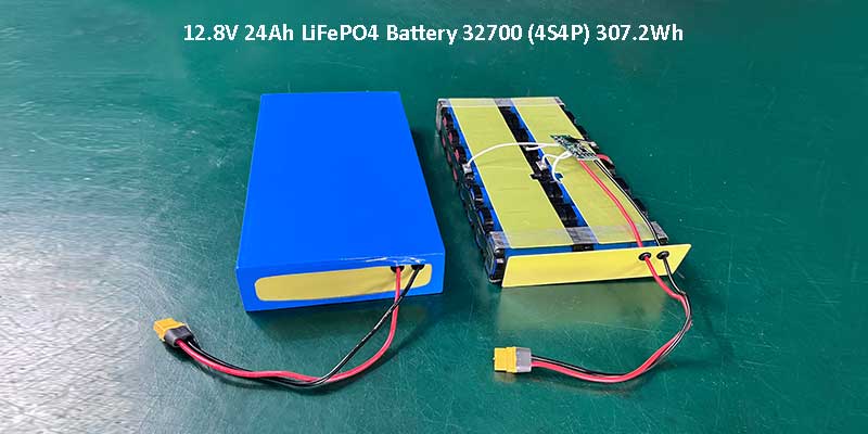
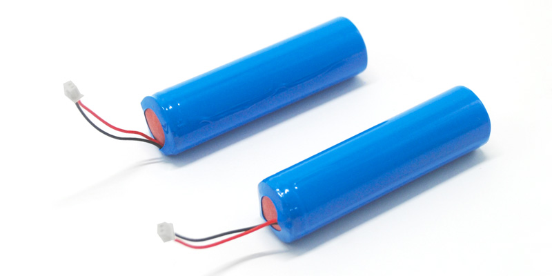
12V 18Ah LiFePO4 Battery Pack for Solar Street Lights
The 12V 18Ah battery pack is designed for compact and medium-power solar street lighting systems.
Key Specifications
- Battery Chemistry: LiFePO4
- Voltage: 12.8V
- Capacity: 18Ah
- Energy: 230Wh
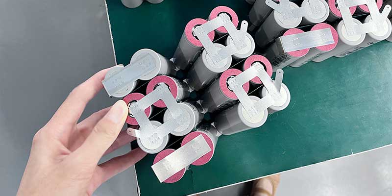
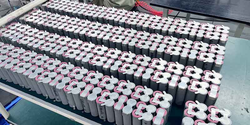
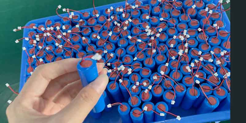
- Cell Configuration: 4S3P
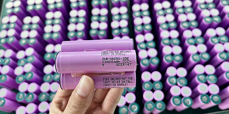
- Cell Type: 32650 6000mAh
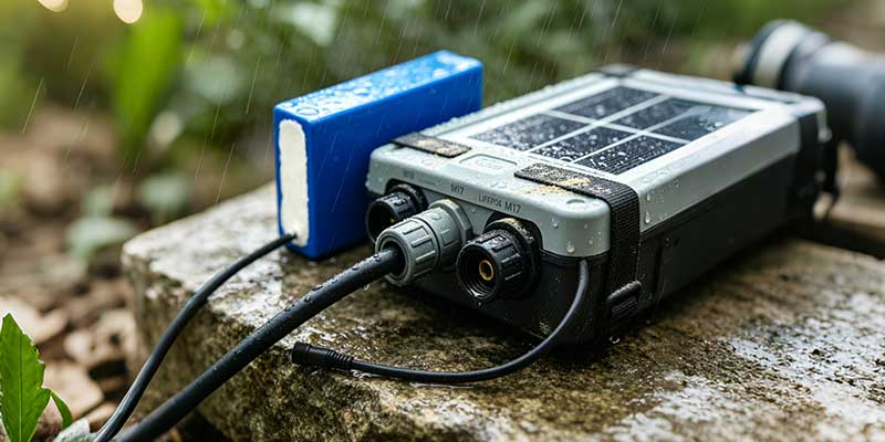
- Waterproof Design
- M17 Connector
- Cable Length: 300mm
- PVC Encapsulation
Typical Applications
The 12V 18Ah battery is suitable for:
- Residential streets
- Pathway lighting
- Community roads
- Parks
- Garden lighting
- Small commercial projects
Because of its compact size, it offers an excellent balance between runtime and installation flexibility.
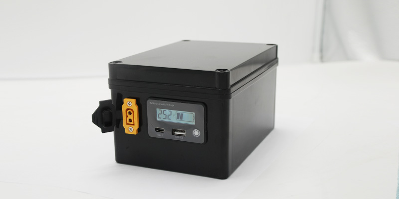
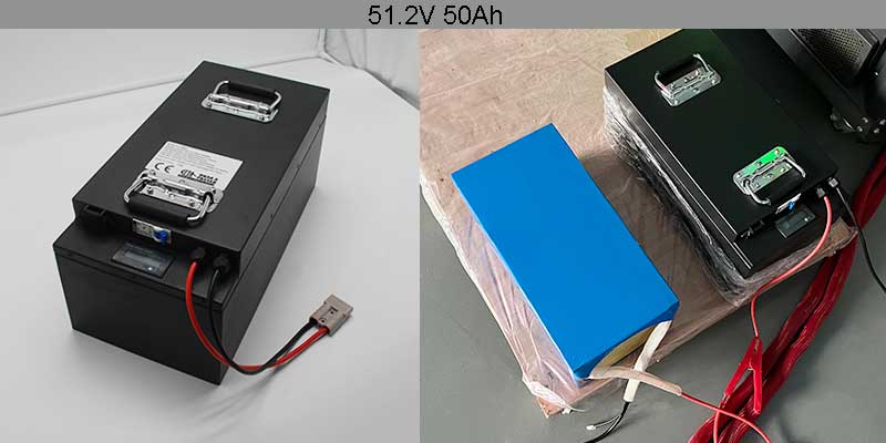
12V 48Ah LiFePO4 Battery Pack for Solar Street Lights
For projects requiring longer autonomy and higher energy storage, the 12V 48Ah battery pack provides a substantial increase in capacity.
Key Specifications
- Battery Chemistry: LiFePO4
- Voltage: 12.8V
- Capacity: 48Ah
- Energy: 614.4Wh
- Cell Configuration: 4S8P
- Cell Type: 32650 6000mAh
- Maximum Charging Current: 24A
- Maximum Continuous Discharge Current: 48A
- Waterproof Protection: IP68
- M17 Connector
- Cable Length: 300mm
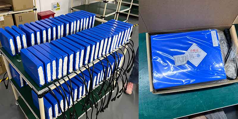
- Double-Layer Blue PVC Protection
Typical Applications
The 48Ah version is commonly selected for:
- High-power solar street lights
- Municipal lighting projects
- Industrial zones
- Parking lots
- Roadway lighting
- Areas with extended nighttime operation
The larger energy reserve helps maintain lighting performance during consecutive cloudy or rainy days.
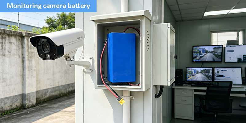
Why Waterproof Protection Is Essential
Outdoor batteries face continuous exposure to:
- Rain
- Humidity
- Dust
- Temperature fluctuations
- Condensation
For this reason, these battery packs are designed with enhanced waterproof measures, including sealed construction and IP68-level protection for demanding environments.
A properly sealed battery pack helps prevent:
- Moisture intrusion
- Corrosion
- Electrical failures
- Premature battery degradation
This is especially important for integrated solar street light systems where the battery is installed inside the pole or fixture housing.
Choosing Between 12V 18Ah and 12V 48Ah
The right battery depends on project requirements.
| Requirement | 12V 18Ah | 12V 48Ah |
| Small street lights | ✓ | |
| Community roads | ✓ | ✓ |
| Municipal projects | ✓ | |
| Long autonomy requirements | ✓ | |
| Compact installation space | ✓ | |
| High-power LED systems | ✓ | |
| Lower initial cost | ✓ | |
| Maximum backup capacity | ✓ |
In many projects, selecting a larger battery can improve reliability during poor weather conditions and reduce complaints related to insufficient lighting duration.
Key Considerations for OEM Solar Street Light Manufacturers
When developing solar lighting products, battery selection should consider more than capacity alone.
1. Waterproof Design
Outdoor reliability begins with proper sealing and environmental protection.
2. Charge and Discharge Capability
The battery must match the controller and LED power requirements.
3. Connector Compatibility
Customized connectors simplify installation and improve system reliability.
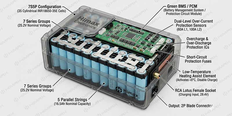
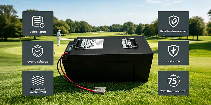
4. Battery Protection System
An integrated protection board helps protect against:
- Overcharge
- Over-discharge
- Overcurrent
- Short circuit
5. Long-Term Supply Stability
Consistent manufacturing quality is essential for large-scale lighting deployments.
Custom Solar Street Light Battery Solutions
Every solar lighting project has unique requirements.
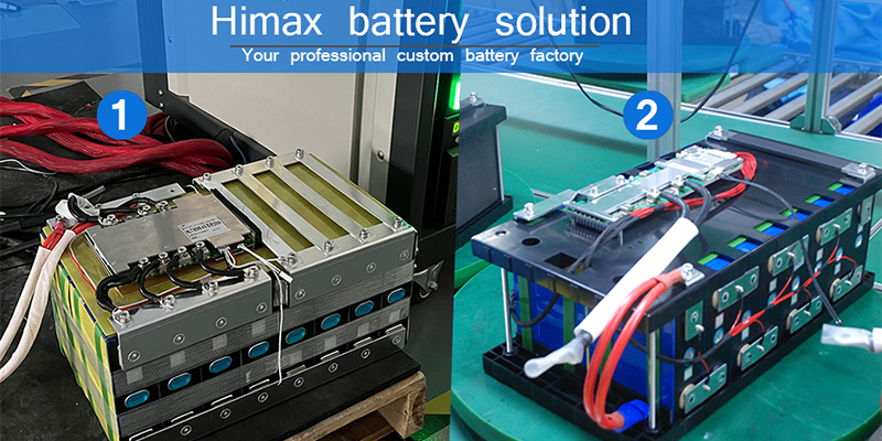
At Himax Electronics, custom battery solutions can include:
- Different capacities
- Customized dimensions
- Connector options
- Cable length modifications
- Waterproof enhancements
- OEM labeling
- Customized battery management systems
This flexibility allows solar street light manufacturers to optimize performance while meeting project-specific requirements.
Related Battery Solutions
Explore our dedicated battery solutions:
- Vacuum Sealer Battery: https://www.himaxelectronics.com/vacuum-sealers-battery/
- Food Processing Battery: https://www.himaxelectronics.com/food-processing-battery/
- Contact Our Engineering Team: https://www.himaxelectronics.com/contact/
Frequently Asked Questions
How long can a 12V 18Ah solar street light battery run?
Runtime depends on LED power consumption, controller settings, and weather conditions. In general, it is suitable for compact and medium-power solar street lighting systems.
Why choose LiFePO4 instead of lead-acid batteries?
LiFePO4 batteries offer longer cycle life, better efficiency, lighter weight, and lower maintenance requirements.
Is IP68 waterproof protection important?
Yes. Outdoor lighting systems are exposed to rain, humidity, and dust. IP68 protection helps improve long-term reliability.
Which battery is better: 12V 18Ah or 12V 48Ah?
The 18Ah version is ideal for smaller systems, while the 48Ah version provides greater energy storage and longer backup time.
Can these battery packs be customized?
Yes. Capacity, dimensions, connectors, waterproofing, and labeling can all be customized according to project requirements.
Conclusion
A reliable Solar Street Light Battery is the foundation of dependable outdoor lighting. Both the 12V 18Ah LiFePO4 battery pack and the 12V 48Ah LiFePO4 battery pack are designed to support solar street light applications with long cycle life, stable performance, and robust waterproof protection.
For smaller lighting systems, the 18Ah version provides an efficient and compact solution. For municipal, industrial, and high-power installations, the 48Ah version delivers the energy reserve needed to maintain lighting performance under demanding conditions.
Contact Us
Looking for a custom Solar Street Light Battery for your next project?
Our engineering team can help you select the right LiFePO4 battery configuration, waterproof design, connector solution, and protection system for your solar lighting application.