新闻与博客 | HIMAX 电子

6.4V 9Ah LiFePO4 battery pack for desert IoT sensor node by Himax Electronics

The Definitive Buyer’s Guide for B2B Engineers & Product Developers

Introduction: Why Power Is the Hardest Problem in Desert IoT

Deploying wireless sensor nodes in arid and desert environments — whether for soil moisture monitoring, groundwater level sensing, wildlife activity detection, or boundary fence status — is no longer a frontier challenge in connectivity or firmware. The hardest unsolved problem remains reliable, maintenance-free power.

Desert deployments face a brutal convergence of conditions: ambient temperatures that swing from below freezing at night to over 55 °C (131 °F) at noon, intense UV exposure, wind-blown particulates, and unpredictable solar irradiance. Standard lead-acid batteries fail within one or two seasons. Generic lithium cells with inadequate BMS protection enter thermal runaway. Alkaline primary cells make remote firmware updates uneconomical.

This guide is written for B2B engineers, hardware product managers, and IoT terminal developers who need a battery solution — not a battery datasheet. We cover the chemistry, the design rationale, real-world failure modes, integration considerations, and the specific advantages of a purpose-built 6.4V 9Ah LiFePO4 pack optimized for desert field deployments.


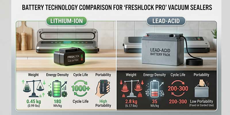
Why LiFePO4 — and Not NMC, LCO, or Lead-Acid?

Battery chemistry is not one-size-fits-all. Here is a direct comparison relevant to outdoor IoT applications:


Chemistry Cycle Life Thermal Stability Voltage Stability Cost/Wh
LiFePO4 (LFP) 2,000–4,000+ Excellent (no thermal runaway) Flat plateau Moderate
NMC / NCA 500–1,500 Poor (runaway risk >60 °C) Sloping Moderate–High
LCO (phone cells) 300–500 Very Poor Sloping High
Lead-Acid (SLA) 200–500 Good but heavy Sloping Low
Alkaline Primary N/A (one-use) Good Declining High (TCO)


Key Insight: LiFePO4’s olivine crystal structure is inherently stable at elevated temperatures. Even at 60 °C — a realistic internal temperature in a sealed enclosure under direct desert sun — LFP cells do not enter thermal runaway. NMC cells in identical conditions can enter runaway above 150–200 °C internal cell temperature, which can be reached far faster than most engineers expect in a poorly ventilated housing.


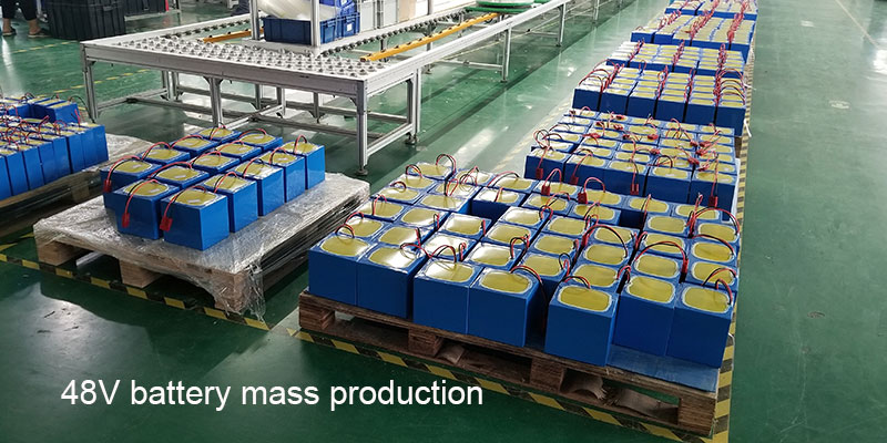
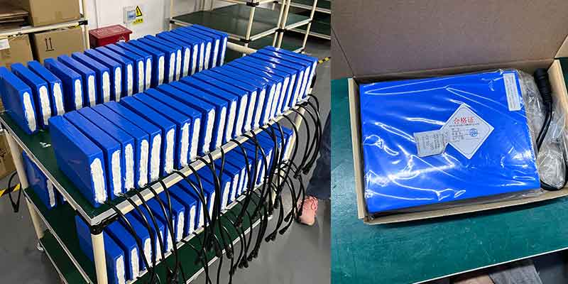
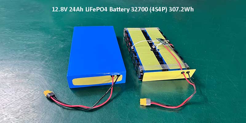
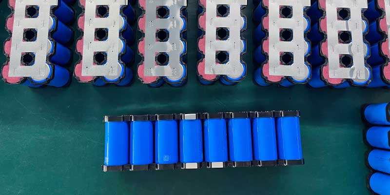
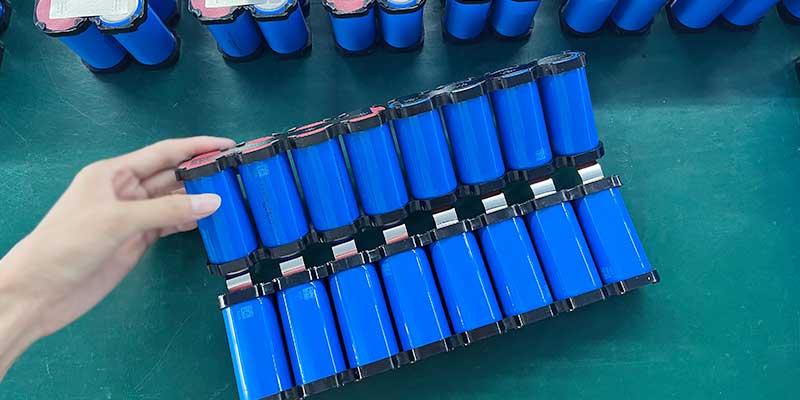
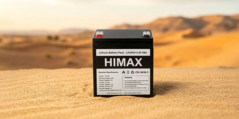
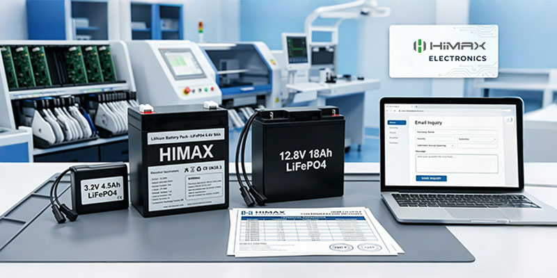
Product Specifications: Himax 6.4V 9Ah LiFePO4 Pack

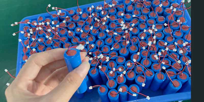
The following specification table reflects the exact configuration available from Himax Electronics (Pack Model: 2S2P, Cell: 26700-B400 / 32700-B000 series):


Nominal Voltage 6.4 V (2S configuration)
Capacity 9 Ah (57.6 Wh)
Cell Configuration 2S2P
Cell Model 26700-B400 (LiFePO4)
Max Charge Current 1.8 A (solar MPPT compatible)
Max Continuous Discharge 9 A
Protection Board (BMS) Standard PCB protection included
Connector Type 2-terminal (positive + negative)
Max Dimensions 90 × 72 × 109 mm
Operating Temperature –20 °C to +60 °C discharge; 0 °C to +45 °C charge
Label / Branding HIMAXBATT | LiFePO4 6.4V 9Ah 57.6Wh | Made in China 32580001
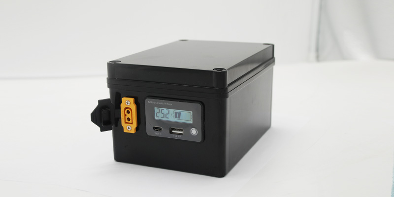
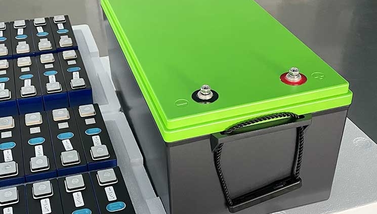
Enclosure Black ABS housing with waterproof vent
Cell Support Frame Optional
Waterproof Rating IP rating per waterproof vent design
Application Desert IoT / Remote Sensor Nodes
Target Region USA
MOQ / Lead Time Contact Himax Electronics for pricing


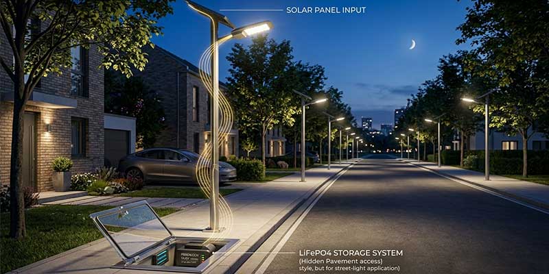
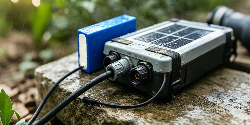
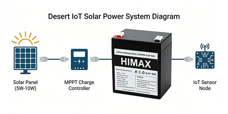
Solar Panel Integration: Matching the Charge Current

The majority of desert IoT deployments use small-format solar panels (5W–20W) with an MPPT charge controller. The 6.4V 9Ah pack is designed for direct compatibility with these systems.

Important design parameters to communicate to your solar system vendor:

  • Max charge current: 1.8 A. Do not exceed without confirming with Himax Electronics.
  • Charge voltage cutoff: 7.3 V (2 × 3.65 V per LFP cell). Overvoltage protection is built into the BMS, but your charge controller should be set correctly.
  • Float / maintenance voltage: 6.6–6.8 V is typical for LFP 2S in field use.
  • Low-temperature charge cutoff: The BMS will block charging below 0 °C to prevent lithium plating. Ensure your controller handles this gracefully.


Engineer’s Note: LFP’s flat discharge curve (approximately 3.2V per cell across 90% of capacity) is a significant advantage for IoT devices that rely on battery voltage for power-good or low-battery signals. Unlike NMC or SLA, the voltage reading is not a reliable state-of-charge proxy; use coulomb counting in your firmware if fuel gauging is required.

LiFePO4 6.4V battery charging from solar panel in desert IoT system

Real-World Application Scenarios

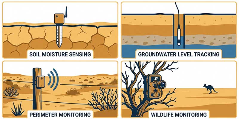
Below are four representative use cases that Himax’s 6.4V 9Ah LiFePO4 pack is actively supporting or qualified for:


  1. Soil Moisture & Agricultural Monitoring

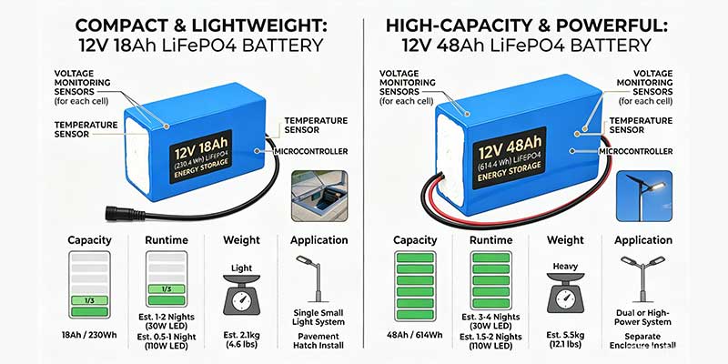
Remote precision agriculture operations in arid regions (US Southwest, California Central Valley, Australian outback) require soil moisture, temperature, and EC sensors that report every 15–60 minutes over LoRaWAN or NB-IoT. Typical node power draw: 2–8 mA average. At 5 mA average, a 9 Ah pack provides over 1,800 hours (75 days) of runtime without solar. With a 5W solar panel and 4 peak-sun-hours/day, nodes run indefinitely.


  1. Groundwater & Water Table Level Monitoring

Hydrogeological monitoring for aquifer depletion, irrigation compliance, or flood early-warning requires sensors placed in wells and boreholes — often in desert or semi-arid terrain. These nodes typically transmit once per hour or less. The key challenge is zero-maintenance operation for 3–5 year cycles. LFP’s 2,000+ cycle life at 80% depth of discharge maps to over 5 years of daily solar charge/discharge cycling.


  1. Boundary & Fence Status Monitoring

Ranch and wildlife reserve operators in the US are deploying wireless fence integrity sensors across thousands of kilometers of boundary. A 6.4V pack can power a sub-GHz wireless node (Semtech SX1276 LoRa class) with periodic tamper/open-circuit detection at under 10 mA average draw. With the integrated waterproof housing and desert-rated LFP cells, these nodes survive seasons without intervention.


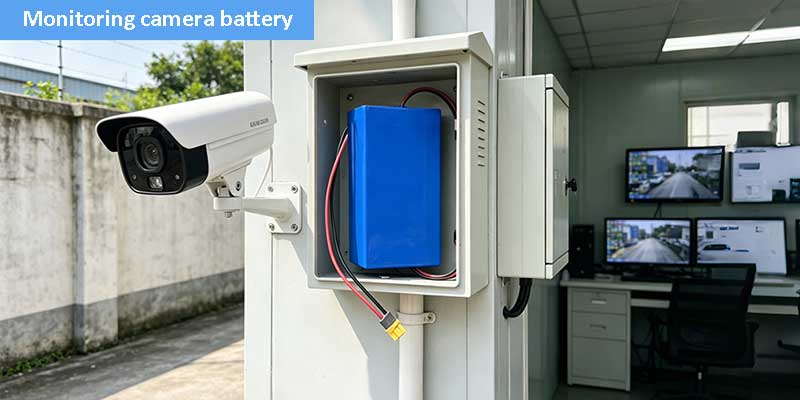
  1. Wildlife Activity & Camera Trap Systems

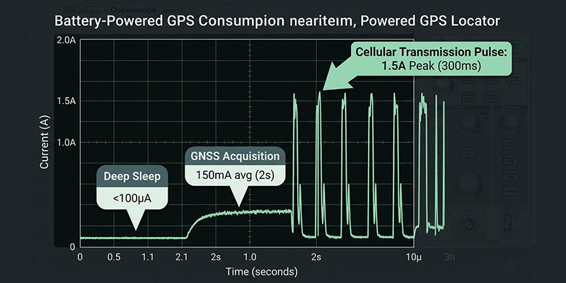
Camera trap and PIR-based wildlife monitoring systems require burst discharge capability — a flash or cellular uplink can draw 1–3 A for 1–5 seconds, dozens of times per day. The 9 A maximum discharge rating of this pack handles these loads with significant margin while the average daily energy use remains low. LFP’s discharge plateau also ensures the MCU and modem receive stable voltage during transmission bursts.

Desert IoT sensor node applications: soil moisture, water level, wildlife monitoring, fence detection


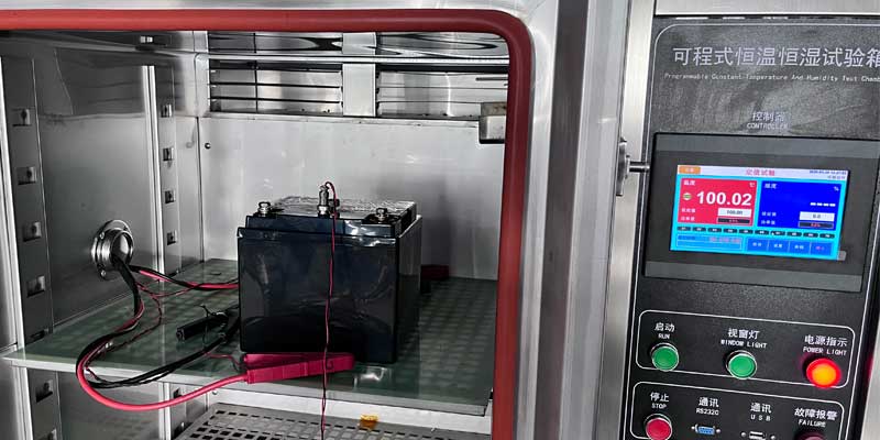
Thermal Engineering Considerations for Desert Enclosures

A battery is only as good as its thermal environment. Placing a 6.4V LFP pack inside a sealed junction box under direct sun in the Mojave can expose it to 70–80 °C — exceeding safe charging limits. Here is what Himax recommends for thermal management:

  • Enclosure color: Matte white or light gray reduces solar absorption by 30–40% vs. black.
  • Orientation: Orient the enclosure so battery faces north (Northern Hemisphere) or away from the sun’s path.
  • Ventilation: The Himax pack includes a waterproof breathable vent. Use an enclosure with passive convection vent panels on the underside to allow rising hot air to escape while excluding dust and insects.
  • Thermal mass: Avoid thin-walled aluminum enclosures which heat and cool rapidly. Polycarbonate or GRP (fiberglass-reinforced polyester) provides better thermal buffering.
  • BMS over-temperature protection: The included PCB protection will disconnect the battery if internal temperature exceeds safe limits. Design your firmware to handle unexpected power-off gracefully.


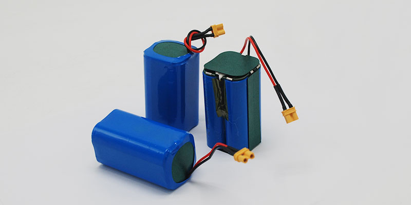
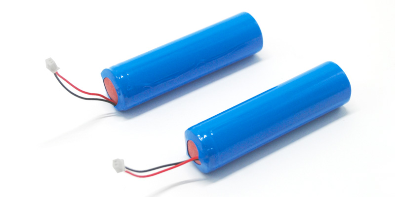
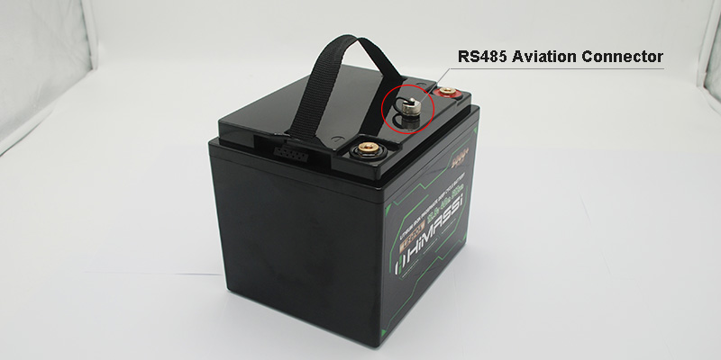
Connector, Wiring, and Integration Notes

The 6.4V 9Ah pack ships with a 2-terminal connector. The following wiring specifics apply:

  • Lead wire: 100 mm from the connector to terminal end. Specify extension length at order if needed.
  • External connector: One Anderson-style red (+), one 2-pin female terminal black (–). Confirm pinout with Himax before PCB layout.
  • Wire gauge: Sized for up to 9 A continuous. Do not use a wire gauge lighter than the factory harness in any field extension.
  • Polarity protection: The BMS includes reverse-polarity protection, but always verify polarity at integration.
  • Ground plane: In LoRaWAN or NB-IoT nodes, ensure the battery negative is not connected to antenna ground without appropriate RF isolation.


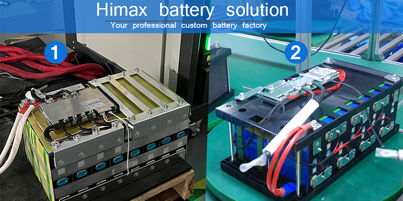
How to Source the Himax 6.4V 9Ah LiFePO4 Pack

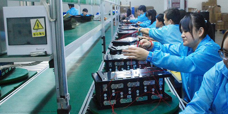
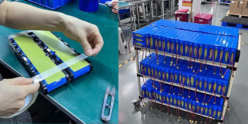
Himax Electronics is a Shenzhen-based battery manufacturer with over a decade of experience in custom lithium packs for industrial, IoT, and renewable energy applications. The 6.4V 9Ah LiFePO4 pack is available as:

  • Standard product (MOQ applies): Shipped with the exact BMS, connector, label, and housing described above.
  • Custom configuration: Modified cell grade, connector type, wire length, enclosure color, or BMS parameters available with engineering discussion.
  • Private-label / OEM: HIMAXBATT label or customer brand print available at volume.


Explore the full IoT battery portfolio: himaxelectronics.com/iot-battery/

Smart plant sensor battery solutions:

himaxelectronics.com/smart-plant-sensors-battery/

Product page — 6.4V 9Ah custom monitoring system pack:

himaxelectronics.com/product-item/6-4v-9ah-custom-lithium-battery-pack-for-monitoring-system/

Get a quote or technical consultation: himaxelectronics.com/contact/


Himax Electronics custom LiFePO4 battery pack inquiry and OEM service for IoT developers

Conclusion: Power Your Desert IoT Deployment Right — the First Time

Selecting the wrong battery chemistry or a poorly engineered pack for a desert IoT deployment is a costly mistake — not at unboxing, but six to eighteen months into the field when cells degrade prematurely, BMS faults trigger silent data loss, or a maintenance visit costs more than the entire original hardware budget.

The 6.4V 9Ah LiFePO4 pack from Himax Electronics is engineered to solve exactly this problem. Designed for 2S2P LFP cells, matched to solar charge constraints, housed in a waterproof black ABS enclosure with a breathable vent, and built to the HIMAXBATT standard — this pack is the right specification for soil monitoring, groundwater sensing, fence detection, and wildlife IoT nodes operating in the US desert environment.

If you are designing a product or deploying a network that needs this level of power reliability, contact the Himax engineering team. We work directly with B2B customers to validate specifications, support firmware integration, and scale from prototype to production.

deep-cycle-12v-24v-48v-lifepo4-battery-pack

HIMAX ELECTRONICS, a leading manufacturer of customized lithium battery solutions, is pleased to introduce its advanced 48V 50Ah LiFePO4 Battery Pack designed specifically for the rapidly growing robotics industry. Engineered to provide reliable power, intelligent communication, and flexible customization, this battery solution is ideal for automated guided vehicles (AGVs), autonomous mobile robots (AMRs), service robots, cleaning robots, warehouse automation systems, and other industrial robotic equipment.

As robotics technology continues to expand across manufacturing, logistics, healthcare, and commercial sectors, the demand for safe, efficient, and long-lasting energy storage solutions has become increasingly important. Modern robots require batteries that not only deliver stable power but also provide intelligent monitoring, flexible integration, and dependable performance in a wide range of operating environments.

The HIMAX 48V 50Ah LiFePO4 Battery Pack has been developed to meet these requirements while offering extensive customization options that help robotics manufacturers build more competitive products.

Designed for Reliable Performance in Demanding Environments

Robotic systems often operate continuously for long periods in warehouses, factories, distribution centers, hospitals, and public facilities. These environments require battery systems that can withstand vibration, dust, accidental water exposure, and daily operational stress.

To ensure durability and reliability, the HIMAX battery is housed in a high-strength plastic enclosure that provides excellent mechanical protection while maintaining a lightweight structure. The battery is rated IP65, offering effective protection against dust ingress and low-pressure water jets from any direction.

This level of protection makes the battery suitable for both indoor and semi-outdoor robotic applications where environmental conditions can vary significantly.

The rugged housing design helps protect the internal battery cells, battery management system (BMS), and communication modules from external damage, contributing to a longer service life and reduced maintenance requirements.
li_ion_48v_100ah

Secure M8 Connectors for Stable Power Delivery

Reliable electrical connections are critical for robotic systems. Loose connectors can cause power interruptions, communication failures, and unexpected equipment downtime.

To address this challenge, the HIMAX 48V 50Ah Battery Pack is equipped with heavy-duty M8 threaded connectors. These industrial-grade connectors provide secure and stable electrical connections, even in applications subject to continuous vibration and movement.

The threaded design prevents accidental disconnection during operation and helps maintain consistent power delivery to motors, controllers, sensors, and other critical components.

This feature is particularly valuable for AGVs, AMRs, and mobile robotic platforms that operate continuously across large facilities.

Built-in LCD Display for Easy Battery Monitoring

Battery monitoring is an important part of robot fleet management. Operators need quick access to battery information in order to maximize operating efficiency and minimize downtime.

To simplify battery management, HIMAX has integrated an LCD display directly into the battery pack. The display provides real-time information, including:

  • Battery voltage
  • Remaining capacity
  • State of charge (SOC)
  • Operating status
  • System information

This user-friendly interface allows operators and maintenance personnel to quickly evaluate battery performance without requiring additional equipment.

The ability to access key battery data directly from the battery pack improves operational efficiency and supports preventive maintenance programs.

Intelligent Bluetooth Connectivity

As smart automation becomes increasingly common, battery systems must provide more than simple energy storage. Modern robotic systems require intelligent communication and remote monitoring capabilities.

The HIMAX battery incorporates Bluetooth technology, allowing users to connect the battery to smartphones, tablets, or other mobile devices through a dedicated application.

Using Bluetooth connectivity, users can remotely monitor battery status, review operating data, check system health, and configure specific battery parameters.

Remote monitoring helps operators identify potential issues before they become critical problems, reducing unexpected downtime and improving overall system reliability.

For robot manufacturers and fleet operators, this capability provides greater visibility into battery performance and simplifies daily maintenance activities.

Advanced Communication for Industrial Automation

Many robotic systems operate as part of larger automation networks. In these environments, battery information must be shared with central control systems to support intelligent energy management.

To meet industrial integration requirements, the HIMAX battery supports serial communication protocols such as RS485 and CAN Bus.

These communication interfaces allow seamless integration with robot controllers, fleet management systems, and industrial automation platforms.

Through real-time data communication, the battery can provide information such as:

  • State of charge (SOC)
  • Battery voltage
  • Current
  • Temperature
  • Battery health status
  • Fault alarms

This information helps robotic systems optimize power consumption, improve operating efficiency, and implement predictive maintenance strategies.

As Industry 4.0 and smart manufacturing continue to develop, intelligent battery communication is becoming an increasingly important feature for advanced robotic systems.

Extensive Customization Capabilities

One of the key advantages offered by HIMAX ELECTRONICS is its strong customization capability.

Different robotic applications often require different battery specifications. A battery solution suitable for a warehouse robot may not be ideal for a service robot, cleaning robot, or outdoor inspection robot.

To address these diverse requirements, HIMAX provides comprehensive customization services, including:

  • Customized battery capacity
  • Customized voltage configurations
  • Modified battery dimensions
  • Specialized enclosure designs
  • Customized discharge and charge parameters
  • Low-temperature operation solutions
  • High-temperature protection solutions
  • Custom BMS programming
  • Customized communication protocols
  • Special connector options

The experienced HIMAX engineering team works closely with customers throughout the development process to ensure the battery solution fully meets the technical requirements of each project.

This flexible approach helps customers accelerate product development while reducing engineering complexity and project risks.

Professional Branding Services

In today’s competitive robotics market, strong brand recognition is essential.

To help customers strengthen their product identity, HIMAX also offers professional branding services. Customer logos can be printed, engraved, or customized directly on the battery housing.

This allows the battery pack to become an integrated part of the customer’s product design rather than simply a hidden component.

Customized branding enhances product appearance, improves market recognition, and supports a consistent corporate image across the entire product portfolio.

Advantages of LiFePO4 Technology

The HIMAX 48V 50Ah Battery Pack utilizes Lithium Iron Phosphate (LiFePO4) chemistry, which is widely recognized as one of the safest and most reliable lithium battery technologies available today.

Compared with traditional lead-acid batteries, LiFePO4 batteries offer several important advantages:

  • Longer cycle life
  • Higher energy efficiency
  • Faster charging capability
  • Lower maintenance requirements
  • Reduced weight
  • Stable voltage output
  • Enhanced safety performance

These benefits make LiFePO4 technology particularly suitable for robotics applications where reliability, efficiency, and long operating life are critical.
48v-lithium-golf-cart-battery

Conclusion

The HIMAX ELECTRONICS 48V 50Ah LiFePO4 Battery Pack delivers a powerful combination of performance, intelligence, durability, and customization. Featuring an IP65-rated enclosure, secure M8 connectors, an integrated LCD display, Bluetooth connectivity, and industrial communication capabilities, it is designed to meet the evolving needs of modern robotic systems.

More importantly, HIMAX’s extensive customization services enable customers to create battery solutions that perfectly match their application requirements, helping them improve product performance and accelerate innovation.

As robotics and automation technologies continue to transform industries worldwide, HIMAX ELECTRONICS remains committed to providing reliable, intelligent, and customized energy solutions that power the future of automation.


12V 18Ah LiFePO4 battery pack for solar street light energy storage

Solar Street Light Battery Guide: 12V LiFePO4 Solutions

By Alden – Battery Engineer – Manufacturing & Quality Control

Solar street lights are expected to work every night, often in remote locations where maintenance is costly and inconvenient. While solar panels and LED fixtures receive most of the attention, the battery pack is the component that determines whether a solar street light can deliver reliable illumination through cloudy weather, seasonal changes, and years of outdoor operation.

At Himax Electronics, we recently supported solar street lighting projects using 12V 18Ah LiFePO4 battery packs and 12V 48Ah LiFePO4 battery packs. Although both batteries serve the same application, they address different runtime and power requirements.

This article explains how these battery packs are used in solar street lighting systems, what makes LiFePO4 technology suitable for outdoor lighting, and how OEM buyers can select the right battery solution.

Why Battery Selection Matters in Solar Street Lights

A solar street light operates as a complete energy system:

  1. Solar panel captures energy during the day.
  2. Charge controller manages charging.
  3. Battery stores energy.
  4. LED light consumes stored energy at night.

When the battery underperforms, the entire lighting system suffers. Common problems include:

  • Reduced lighting hours
  • Dim illumination before dawn
  • Frequent battery replacement
  • System downtime during cloudy periods
  • Increased maintenance costs

For municipalities, contractors, and lighting equipment manufacturers, battery reliability directly impacts project success.

The Advantages of LiFePO4 Batteries for Solar Street Lights

Compared with traditional lead-acid batteries, LiFePO4 battery technology offers several important benefits.

Longer Cycle Life

Solar street lights charge and discharge every day. This means the battery may experience hundreds of cycles annually.

LiFePO4 cells typically provide significantly longer cycle life than conventional lead-acid alternatives, helping reduce replacement frequency and long-term operating costs.

Improved Safety

Safety is critical for batteries installed in public areas.

LiFePO4 chemistry offers:

  • Excellent thermal stability
  • Reduced risk of thermal runaway
  • Better tolerance to outdoor temperature variations
  • Reliable long-term operation

Higher Energy Efficiency

A more efficient battery stores and delivers energy with lower losses.

This allows solar lighting systems to:

  • Maximize harvested solar energy
  • Extend nighttime runtime
  • Improve overall system efficiency

Lightweight Construction

LiFePO4 batteries are lighter than comparable lead-acid batteries, making installation easier and reducing structural requirements.

12V 48Ah LiFePO4 battery pack with IP68 protection for solar street lighting

12V 18Ah LiFePO4 Battery Pack for Solar Street Lights

The 12V 18Ah battery pack is designed for compact and medium-power solar street lighting systems.

Key Specifications

  • Battery Chemistry: LiFePO4
  • Voltage: 12.8V
  • Capacity: 18Ah
  • Energy: 230Wh
  • Cell Configuration: 4S3P
  • Cell Type: 32650 6000mAh
  • Waterproof Design
  • M17 Connector
  • Cable Length: 300mm
  • PVC Encapsulation

Typical Applications

The 12V 18Ah battery is suitable for:

  • Residential streets
  • Pathway lighting
  • Community roads
  • Parks
  • Garden lighting
  • Small commercial projects

Because of its compact size, it offers an excellent balance between runtime and installation flexibility.

12V 48Ah LiFePO4 Battery Pack for Solar Street Lights

For projects requiring longer autonomy and higher energy storage, the 12V 48Ah battery pack provides a substantial increase in capacity.

Key Specifications

  • Battery Chemistry: LiFePO4
  • Voltage: 12.8V
  • Capacity: 48Ah
  • Energy: 614.4Wh
  • Cell Configuration: 4S8P
  • Cell Type: 32650 6000mAh
  • Maximum Charging Current: 24A
  • Maximum Continuous Discharge Current: 48A
  • Waterproof Protection: IP68
  • M17 Connector
  • Cable Length: 300mm
  • Double-Layer Blue PVC Protection

Typical Applications

The 48Ah version is commonly selected for:

  • High-power solar street lights
  • Municipal lighting projects
  • Industrial zones
  • Parking lots
  • Roadway lighting
  • Areas with extended nighttime operation

The larger energy reserve helps maintain lighting performance during consecutive cloudy or rainy days.

Solar street light system powered by high-cycle-life LiFePO4 battery technology

Why Waterproof Protection Is Essential

Outdoor batteries face continuous exposure to:

  • Rain
  • Humidity
  • Dust
  • Temperature fluctuations
  • Condensation

For this reason, these battery packs are designed with enhanced waterproof measures, including sealed construction and IP68-level protection for demanding environments.

A properly sealed battery pack helps prevent:

  • Moisture intrusion
  • Corrosion
  • Electrical failures
  • Premature battery degradation

This is especially important for integrated solar street light systems where the battery is installed inside the pole or fixture housing.

Choosing Between 12V 18Ah and 12V 48Ah

The right battery depends on project requirements.

Requirement 12V 18Ah 12V 48Ah
Small street lights
Community roads
Municipal projects
Long autonomy requirements
Compact installation space
High-power LED systems
Lower initial cost
Maximum backup capacity

In many projects, selecting a larger battery can improve reliability during poor weather conditions and reduce complaints related to insufficient lighting duration.

Key Considerations for OEM Solar Street Light Manufacturers

When developing solar lighting products, battery selection should consider more than capacity alone.

1. Waterproof Design

Outdoor reliability begins with proper sealing and environmental protection.

2. Charge and Discharge Capability

The battery must match the controller and LED power requirements.

3. Connector Compatibility

Customized connectors simplify installation and improve system reliability.

4. Battery Protection System

An integrated protection board helps protect against:

  • Overcharge
  • Over-discharge
  • Overcurrent
  • Short circuit

5. Long-Term Supply Stability

Consistent manufacturing quality is essential for large-scale lighting deployments.

Waterproof LiFePO4 battery pack used in outdoor solar street lights

Custom Solar Street Light Battery Solutions

Every solar lighting project has unique requirements.

At Himax Electronics, custom battery solutions can include:

  • Different capacities
  • Customized dimensions
  • Connector options
  • Cable length modifications
  • Waterproof enhancements
  • OEM labeling
  • Customized battery management systems

This flexibility allows solar street light manufacturers to optimize performance while meeting project-specific requirements.

Related Battery Solutions

Explore our dedicated battery solutions:

Frequently Asked Questions

How long can a 12V 18Ah solar street light battery run?

Runtime depends on LED power consumption, controller settings, and weather conditions. In general, it is suitable for compact and medium-power solar street lighting systems.

Why choose LiFePO4 instead of lead-acid batteries?

LiFePO4 batteries offer longer cycle life, better efficiency, lighter weight, and lower maintenance requirements.

Is IP68 waterproof protection important?

Yes. Outdoor lighting systems are exposed to rain, humidity, and dust. IP68 protection helps improve long-term reliability.

Which battery is better: 12V 18Ah or 12V 48Ah?

The 18Ah version is ideal for smaller systems, while the 48Ah version provides greater energy storage and longer backup time.

Can these battery packs be customized?

Yes. Capacity, dimensions, connectors, waterproofing, and labeling can all be customized according to project requirements.

Conclusion

A reliable Solar Street Light Battery is the foundation of dependable outdoor lighting. Both the 12V 18Ah LiFePO4 battery pack and the 12V 48Ah LiFePO4 battery pack are designed to support solar street light applications with long cycle life, stable performance, and robust waterproof protection.

For smaller lighting systems, the 18Ah version provides an efficient and compact solution. For municipal, industrial, and high-power installations, the 48Ah version delivers the energy reserve needed to maintain lighting performance under demanding conditions.

Contact Us

Looking for a custom Solar Street Light Battery for your next project?

Our engineering team can help you select the right LiFePO4 battery configuration, waterproof design, connector solution, and protection system for your solar lighting application.

👉 https://www.himaxelectronics.com/contact/

14.8V 2200mAh lithium-ion battery pack for vacuum sealer applications

Introduction

Vacuum Sealer Battery is a critical power source for cordless food packaging machines, directly affecting suction strength, sealing temperature stability, and overall packaging performance.

Modern portable vacuum sealers require a battery system that can support both vacuum pump motor startup currents and continuous heating sealing loads without voltage drop.

A 14.8V 2200mAh lithium-ion vacuum sealer battery pack is widely used in OEM cordless sealing equipment because it offers stable discharge performance, compact size, and long cycle life.

For manufacturers developing cordless vacuum sealing machines or mobile food packaging systems, selecting the right battery pack is essential for ensuring consistent sealing quality and user experience.

About the Author

Nath is a Battery Engineer specializing in lithium battery design, cell performance optimization, and OEM energy storage solutions. His work focuses on improving discharge stability and helping manufacturers develop reliable battery systems for portable electronic and industrial equipment.

Featured Answer: What is a Vacuum Sealer Battery?

A vacuum sealer battery is a rechargeable lithium-ion battery pack designed to power portable vacuum sealing machines. It provides stable voltage for both the vacuum pump motor and heating sealing system, enabling cordless operation for food packaging equipment.

Lithium-ion Battery for Cordless Food Packaging Machines

Vacuum sealer battery packs are mainly used in cordless vacuum sealing systems where stable energy output is required for suction and heat sealing processes.

Common search terms include:

  • cordless vacuum sealer battery pack
  • rechargeable vacuum food sealer battery
  • 8V lithium ion vacuum sealer battery
  • portable food sealing machine battery

These systems are widely used in households, commercial kitchens, and mobile food processing applications.

👉 Explore full food industry battery solutions:
https://www.himaxelectronics.com/food-processing-battery/

Why 14.8V Lithium-Ion Battery Is Ideal for Vacuum Sealers

14.8V=3.7V×414.8V = 3.7V \times 414.8V=3.7V×4

A 14.8V lithium-ion battery pack is typically built using a 4-series (4S) lithium cell configuration, making it suitable for vacuum sealing machines requiring stable medium-voltage power.

Key advantages include:

  • Strong startup current support for vacuum pumps
  • Stable output for heating sealing bars
  • Compact size with balanced runtime
  • Higher efficiency than 12V lead-acid systems

14.8V 2200mAh Vacuum Sealer Battery Specifications

Item Value
Battery Chemistry Lithium-Ion
Configuration 4S1P (18650 cells)
Nominal Voltage 14.8V
Capacity 2200mAh
Energy 32.56Wh
Protection Built-in BMS
Rechargeable Yes
Customization OEM/ODM supported

👉 View product details:
https://www.himaxelectronics.com/product-item/14-8v-2200mah-li-ion-battery/

Custom connector and cable design for portable vacuum sealer battery pack

Common Power Issues in Vacuum Sealers and Solutions

Weak suction performance

Occurs when battery voltage drops during vacuum pump startup.
✔ Solution: high-discharge lithium-ion battery pack with stable voltage output.

Inconsistent sealing quality

Heating elements require stable power input for uniform sealing.
✔ Solution: low internal resistance lithium cells with BMS protection.

Short runtime

Insufficient capacity leads to frequent charging interruptions.
✔ Solution: optimized 2200mAh or higher capacity battery design.

Applications of Lithium-ion Battery Packs

  • Cordless vacuum sealing machines
  • Portable food packaging equipment
  • Commercial kitchen sealing systems
  • Mobile food processing devices
  • Outdoor food preservation tools
  • Rechargeable food storage devices
  • Compact vacuum packaging systems

Rechargeable lithium-ion battery powering a cordless vacuum sealing machine

How to Choose the Right Vacuum Sealer Battery

When selecting a battery pack, OEM manufacturers should evaluate:

1. Voltage compatibility

Ensure match with vacuum pump and heating system (typically 12V–16V range).

2. Discharge performance

Must support high startup current without voltage drop.

3. Cycle life

High-quality lithium-ion batteries support 500+ cycles.

4. Mechanical design

Battery size, connector type, and wiring must match device structure.

5. Safety protection

Includes:

  • Overcharge protection
  • Over-discharge protection
  • Overcurrent protection
  • Short circuit protection

OEM Vacuum Sealer Battery Customization

We provide OEM/ODM battery solutions for vacuum sealing equipment, including:

  • Voltage and capacity customization
  • Connector and cable design
  • Battery pack dimension optimization
  • BMS protection system configuration
  • Private label branding

Common Battery Problems in Vacuum Sealers

If the battery is not properly designed, users may experience:

  • Reduced suction power due to voltage drop
  • Inconsistent sealing temperature
  • Short operating time between charges
  • Premature battery aging

A properly engineered lithium-ion battery pack solves these issues effectively.

Lithium-Ion vs Lead-Acid Batteries for Vacuum Sealers

Feature Lithium-Ion Lead-Acid
Energy Density High Low
Weight Light Heavy
Cycle Life Long Short
Charging Speed Fast Slow
Maintenance Low High
Portable Use Excellent Limited

High-performance battery pack for food packaging and vacuum sealing

Frequently Asked Questions

Q1. What is the best battery for a cordless vacuum sealer?
A 14.8V lithium-ion battery pack is the most common solution.

Q2. How long does a vacuum sealer battery last?
Typically 500+ charge cycles depending on usage conditions.

Q3. Can I use a 12V battery instead of 14.8V?
Not recommended, as it may reduce suction and sealing performance.

Q4. What affects runtime?
Pump power, heating load, usage frequency, and battery capacity.

Q5. Can vacuum sealer batteries be customized?
Yes, OEM customization is fully supported.

Key Takeaways

  • 8V lithium-ion batteries provide stable power for cordless vacuum sealers
  • Battery performance directly affects suction and sealing quality
  • OEM customization improves product reliability
  • Proper battery selection reduces failure rates and maintenance costs

Conclusion

A Vacuum Sealer Battery is a core component in portable food packaging equipment, directly determining performance stability and user experience.

The 14.8V 2200mAh lithium-ion battery pack offers an optimal balance of power, size, and durability for modern cordless vacuum sealing systems.

Contact Us

Need a custom vacuum sealer battery solution?

👉 Contact us:
https://www.himaxelectronics.com/contact/

Himax Electronics order specification sheet for 25.6V 10Ah LiFePO4 battery pack with RS485 communication, designed as lead-acid replacement for electric walker and rollator applications — North America market

By Shawn  |  Battery Engineer – Power System Design, Himax Electronics

Case Study  ·  LiFePO4 Power Systems  ·  Medical Mobility

LiFePO4 battery for electric walker is not just an upgrade — it’s a necessity. Let me be direct with you: lead-acid batteries do not belong in modern electric walkers. They never really did. Therefore, this case study walks through a 25.6V 10Ah LiFePO4 battery pack we recently engineered for an electric walker OEM — and explains, from a power systems engineer’s perspective, exactly why this chemistry and configuration was the only logical answer.


Why a LiFePO4 Battery for Electric Walker Beats Lead-Acid Every Time

An electric walker — or power rollator — carries a person who often depends on it for basic daily mobility. That’s a fundamentally different use case from a power tool or an e-bike. The battery doesn’t just deliver performance; it determines safety, portability, and trust. A device this important deserves a power source engineered with the same care as the frame it’s bolted to.

When this OEM came to us, they were running a lead-acid battery. Their engineers knew it was a weak link. The pack was too heavy, runtime was inconsistent, and the battery offered no way to tell the device — or the user — how much charge remained. They needed something smarter. We built them exactly that. In short, that’s exactly why a high-quality LiFePO4 battery for electric walker makes such a measurable difference.


Full Specification Breakdown

Here’s what we built, and why each parameter was chosen:


Parameter Value
Chemistry LiFePO4 (Lithium Iron Phosphate)
Configuration 8S2P (8 series × 2 parallel)
Cell Model 26700 / 5000mAh per cell
Nominal Voltage 25.6V
Fully Charged Voltage 29.2V
Capacity 10Ah
Max Discharge Current 10A (device operating power)
Max Charge Current 5A (solar / adapter compatible)
Communication RS485 with RJ45 waterproof connector
Charge Connector AMASS XT60-F (with dust cap)
Wire Spec 12AWG, UL1015
Charge wire length 150mm (±20mm)
Discharge wire length 75mm (±20mm)
Max Dimensions L181 × W76 × H165mm (±2mm)
Housing Black ABS — lead-acid form factor replacement
Waterproofing Yes
Certifications Reach, RoHS, MSDS, Air Transport Assessment
Target Market North America


The 8S2P topology is the key insight here. For example, eight cells in series gives us 25.6V — exactly the voltage profile the walker’s motor controller expects, matching or exceeding the legacy lead-acid pack voltage with far superior stability. Two cells in parallel doubles the capacity to 10Ah without increasing the footprint beyond the original housing envelope.

26700 LiFePO4 cells in 8S2P configuration with nickel strip welding and pink insulation rings during OEM battery pack assembly at Himax Electronics factory, for electric walker power systems

The Case Against Lead-Acid in Medical Mobility Devices

I’ve reviewed a lot of battery specs over my career. And when I see a lead-acid pack in a product that a person has to carry, lift, or push daily, I know immediately where the engineering debt is hiding.


Criteria LiFePO4 25.6V Sealed Lead-Acid NiMH
Weight Light (~1.5 kg) Heavy (4–6 kg) Moderate
Cycle Life 2000+ cycles 300–500 cycles 500–800 cycles
Voltage Sag Flat / stable Significant sag Moderate sag
RS485 Support Yes (smart comms) No No
Safe indoors Yes — no acid/gas Risk of acid/gas Yes
Lifespan 8–10 years 2–3 years 3–5 years


Obviously, the weight difference alone justifies switching to a LiFePO4 battery for electric walker. A sealed lead-acid battery at 25V and 10Ah weighs roughly 4–6 kg. Our LiFePO4 pack comes in around 1.5 kg. For a user who already has limited mobility, that’s not a minor improvement — it’s a life-quality difference.

Moreover, that’s before we get to cycle life. A lead-acid pack in daily-use conditions typically lasts 300–500 charge cycles. Our 26700 LiFePO4 cells deliver 2,000+ cycles — meaning the battery will likely outlast the walker itself.


RS485 Communication: The Smart Feature Your LiFePO4 Battery for Electric Walker Needs

Most battery engineers focus on voltage, capacity, and current. I do too — but on this project, the RS485 communication interface was what I found genuinely compelling. It’s the kind of feature that separates a commodity battery from a smart power system. Consequently, when you integrate RS485 into a LiFePO4 battery for electric walker, you turn a dumb power source into a smart mobility asset.

What RS485 enables in practice

Real-time state of charge display. The walker’s control panel can show the user exactly how much battery remains — not a guess, not a LED bar that drops suddenly, but accurate, real-time capacity data pulled directly from the BMS over RS485.

In terms of voltage, the system can monitor per-cell group voltage, detect imbalances early, and alert the device firmware before a problem becomes a failure. In a medical mobility context, that’s meaningful.

When it comes to capacity calibration, the RS485 protocol allows the device to adjust displayed capacity based on actual BMS readings rather than estimated state-of-charge curves — more accurate for the end user, fewer support calls for the OEM.

Design note: The customer specified that the RS485 display must show voltage and capacity accurately, adjusted to the smallest readable unit. We tuned the BMS communication parameters to match their display driver’s polling rate, ensuring the readout is smooth and responsive under normal operating loads.

25.6V LiFePO4 electric walker battery pack showing XT60-F charge connector and RJ45 RS485 communication port for real-time voltage and capacity monitoring in mobility aid devices

BMS Configuration: Designed for Real-World Mobility Use

A walker battery lives a different life than an EV pack or a solar storage unit. It charges once a day (or once every few days). It discharges slowly and steadily — no aggressive peaks. It sits in a warm environment. Above all, it needs to be reliable without any user interaction whatsoever.

The BMS on this pack was configured with exactly that operating profile in mind:


Protection / Feature Specification
Overcharge cutoff 25.6V → 29.2V (8S fully charged)
Over-discharge cutoff ≥ 16V (BMS protection threshold)
Max continuous discharge 10A
Max charge current 5A (solar / adapter compatible)
Cell balancing Yes — passive balancing
Communication protocol RS485 (real-time voltage/capacity display)
Short circuit protection Yes
Operating temperature Specified per design


The 5A charge limit is deliberate — it protects the cells from aggressive solar or fast-charge inputs while remaining fully compatible with standard adapter chargers. The 10A discharge ceiling matches the walker’s maximum motor draw with comfortable headroom, so the BMS never trips under normal use.

A well-designed BMS for a medical device is one the user never thinks about. It just works — every time, all the time, for years.”


Cell Selection for a LiFePO4 Battery for Electric Walker: Why 26700 Works

The 26700 form factor (26mm diameter, 70mm length) sits between the compact 18650 and the high-capacity 32700. Specifically for this application, it’s the right balance: enough capacity per cell to build a 10Ah pack in just 2P (parallel) rather than needing 4P or more, which keeps the pack compact enough to fit the lead-acid footprint.

At 5,000mAh per cell, two in parallel gives us 10Ah — precisely matching the OEM’s runtime requirement. The 8S topology then stacks eight of these pairs in series, stepping voltage up from 3.2V per cell to 25.6V nominal — the exact voltage the walker controller expects.

LiFePO4 chemistry in the 26700 format also brings excellent thermal stability. Walkers used indoors and outdoors across North American climate ranges need a cell that handles both winter cold storage and summer ambient temperatures without meaningful capacity loss.


Housing & Mechanical Design: A True Lead-Acid Drop-In

One of the harder constraints on this project was the mechanical envelope. The OEM’s chassis was designed for a standard lead-acid battery. Any replacement had to fit the same bolt pattern, connector orientation, and external dimensions — otherwise the customer faced a costly retool of their housing design.

As a result, we engineered the pack to fit within L181 × W76 × H165mm(±2mm) — staying within the original lead-acid housing dimensions. The black ABS enclosure mimics the form factor exactly. The XT60-F charge port and RJ45 RS485 connector are mounted in the same orientation as the customer’s wiring harness, so installation is genuinely plug-and-play.

Waterproofing was included as standard on this build — appropriate for a device that might be used in light rain or cleaned with damp cloths in a healthcare setting.


Certification: Built for the North American Market

Selling a lithium battery pack in North America — particularly in a medical-adjacent application — means documentation isn’t optional. This pack was built to comply with:

  • Reach — materials compliance, confirming no restricted substances
  • RoHS — restriction of hazardous substances in electronics
  • MSDS — material safety data for transport and handling
  • Air Transport Assessment — enabling air freight where required

The customer also specified a 5A fuse requirement inside the battery — an additional protection layer that we incorporated into the BMS circuit design rather than adding it as an external component, keeping the form factor intact.

Completed 25.6V 10Ah LiFePO4 battery pack in black ABS housing — a direct lead-acid replacement for electric walkers, featuring RS485 smart BMS, Reach and RoHS certification for North American OEM customers

Manufacturing & Quality Process

My role isn’t just design — I’m also involved in the production process. Here’s what this pack’s build flow looked like:


  1.  Cell matching:  Every 26700 cell tested for open-circuit voltage and internal resistance. Cells are paired by matching IR values before entering the 2P parallel groups — unmatched cells cause cross-current and degrade faster.
  2.  Nickel strip welding:  Cells assembled in the 8S2P topology and spot-welded with nickel strips. Weld points inspected under load — high resistance welds are flagged and reworked before proceeding.
  3.  BMS integration & RS485 tuning:  BMS installed and communication parameters programmed to match the customer’s display driver spec. RS485 output verified against their firmware at the agreed polling rate.
  4.  Waterproofing & housing:  Pack sealed into the black ABS housing, connectors torqued and tested for IP rating. Wire routing fixed with cable anchors as specified in the customer’s wiring diagram.
  5.  Aging & capacity test:  Full charge-discharge cycle logged against rated capacity. Internal resistance measured post-cycle. Any pack below 98% of rated capacity is rejected from the shipment batch.
  6.  Labeling & documentation:  Production date printed on cells. Battery serial number label applied per the customer’s label artwork. Reach/RoHS label and QR code applied to battery and inner packaging. MSDS, OQA inspection report, and delivery note included per shipment requirements.


Why This Matters Beyond the Spec Sheet

I work on a lot of battery projects. Industrial, consumer, marine, medical. And I’ll be honest — the ones I find most meaningful are the ones that end up in the hands of people who actually need reliable power to stay mobile and independent.

An electric walker isn’t a luxury product. For many users, it’s a prerequisite for a functional day. Consider what the battery inside it must do: start every morning, last through a full day of use, charge reliably overnight, and repeat that for years — without the user ever thinking about it.

Designing a reliable LiFePO4 battery for electric walker isn’t just about cells — it’s about understanding the user’s daily reality.

That’s the standard we hold ourselves to at Himax. Not just meeting the spec. Engineering to the use case.

Nevertheless, if you’re developing or sourcing batteries for mobility aids… I’d genuinely encourage you to read the comparison table again. The engineering case for a LiFePO4 battery for electric walker is overwhelming. Ultimately, the only remaining question is who builds it right.


Ready to Upgrade Your Mobility Device Battery?

Whether you need a direct lead-acid replacement or a fully custom LiFePO4 pack with RS485 communication, our engineering team at Himax Electronics can take your spec from concept to certified production. Let’s talk about your power requirements.


→  Electric Vehicle & Mobility Battery Solutions

See our 25.6V 10Ah LiFePO4 battery for electric walker product page

→  Contact Himax for a Custom OEM Quote

LiFePO4 battery for security camera

By Alden  |  Battery Engineer — Manufacturing & Quality Control, Himax Electronics


A surveillance camera that loses power at the wrong moment isn’t just an inconvenience — it’s a failure. Choosing the right batteries for security systems is the first step to prevent that. So in this post, I walk through a real battery pack we engineered specifically for 24/7 monitoring devices: what we built, why we made every decision we did, and most importantly, what makes a LiFePO4 battery the right backbone for serious security applications.


The Power Problem No One Talks About

Typically, when security system integrators evaluate their installations, they spend hours choosing lenses, night vision specs, and storage capacity. However, power rarely gets the same attention — until something fails.

The reality is that batteries for security systems carry a disproportionate responsibility. After all, a camera is only as reliable as the energy source behind it. Whether it’s grid outages, brownouts, or solar input fluctuations — the battery is, ultimately, the last line of defense between a live feed and a black screen.

This project started with exactly that concern. A customer building professional monitoring equipment needed a compact, dependable battery pack that could handle continuous discharge loads, survive temperature variation, accept solar charge input, and pass market certification requirements. They came to us at Himax Electronics, and what we built together tells a good story about what serious battery engineering actually looks like. That’s how we design all our batteries for security systems — with no compromise on reliability.

LiFePO4 12.8V 24Ah battery pack order specification sheet showing 4S4P configuration, BMS parameters, and product requirements for security surveillance systems — Himax Electronics

Full Specification Breakdown

Let’s start with the numbers. To be precise, here’s what this battery pack is built around:


Parameter Value
Chemistry LiFePO4 (Lithium Iron Phosphate)
Configuration 4S4P (4 series × 4 parallel)
Cell Model 32700 / 3.2V / 6000mAh per cell
Nominal Voltage 12.8V
Capacity 24Ah
Energy ≈ 307.2Wh
Max Continuous Discharge 10A
Charge Current ≤ 1C (solar input compatible)
Connector XT60 Female
Wire Length 200mm
Dimensions 42.5 × 265.0 × 136.0 mm
Enclosure Blue PVC heat shrink
Shipping SOC 50%


To put it in perspective, 307.2Wh in a package that fits inside a compact monitoring enclosure. That’s the core engineering challenge: squeezing serious energy density into a geometry-constrained form factor without compromising safety or serviceability.

Assembled 12.8V 24Ah LiFePO4 battery pack in blue PVC enclosure with XT60 connector, alongside internal structure showing BMS board and 32700 cell assembly for CCTV backup power

Why 32700 LiFePO4 Cells Are the Ideal Batteries for Security Systems

Every battery pack decision starts with the cell. That’s because, for security applications, I consistently reach for LiFePO4 chemistry — and, more specifically, the 32700 form factor when high capacity is needed in a cylindrical format.

For example, the 32700 cell — 32mm diameter, 70mm length — offers one of the best capacity-to-size ratios in the cylindrical cell world. At 3.2V and 6,000mAh per cell, it brings substantial energy into each slot of the battery bracket — consequently, without the heat accumulation concerns you get with denser NMC chemistries.

Understanding the 4S4P Configuration

This pack uses 16 cells total, arranged in a 4S4P topology.
Specifically, the “4S” configuration means four cells in series — which multiplies voltage: 4 × 3.2V = 12.8V nominal.
Meanwhile, the 4P arrangement multiplies capacity: 4 × 6,000mAh = 24,000mAh (24Ah).
As a result, it’s an elegant arithmetic that turns sixteen modest cylinders into a powerful, unified energy source.

Why this matters for security use: Series gives you the voltage headroom to run standard 12V monitoring equipment directly. Parallel gives you the runtime — at a typical 3–5A draw from a surveillance controller, this pack delivers 5–8 hours of backup capacity without breaking a sweat.


LiFePO4 vs. The Alternatives: An Honest Comparison

When customers ask me what battery chemistry to use for their security system battery, I always walk through the trade-offs honestly.


Criteria LiFePO4 Lead-Acid NMC Li-ion
Cycle Life 2000+ cycles 300–500 500–1000
Thermal Safety Excellent Moderate Moderate
Weight Light Heavy Lightest
Voltage Stability Very flat curve Drooping Good
Suitable for always-on Yes Limited Yes (with care)


Unsurprisingly, for an always-on, low-maintenance deployment — which is exactly how most security systems operate — LiFePO4 wins convincingly. In fact, It’s flat discharge curve means the devices it powers see stable voltage throughout the cycle — rather than a gradual sag that can destabilize camera electronics.

32700 LiFePO4 cells arranged in 4S4P configuration on cell holder brackets during OEM battery pack assembly process at Himax Electronics factory

The BMS: Designing for “Set It and Forget It” Reliability

Analogously, a battery without a good BMS is like a security camera without tamper protection. The battery management system is what keeps this pack safe during the years of unattended operation that a typical security installation demands.

Here’s how we configured the BMS for this project:


Protection Feature Parameter
Overcharge cutoff 14.6V ± 0.05V
Over-discharge cutoff 10V ± 0.05V
Max continuous discharge 10A
Short circuit protection Yes
Overcurrent protection Yes
Cell balancing Yes (passive balancing)
Operating temperature −10°C ~ +50°C


First, to ensure reliable solar charging, the charge parameters were specifically aligned with solar input compatibility. After all, solar chargers can be erratic: clouds pass, panels overheat, charge controllers vary. Therefore, consequently, the BMS had to absorb that variability without ever letting the cells see dangerous voltages. Moreover, the 14.6V ceiling is exactly right for 4S LiFePO4 — it gives enough headroom for full charge without risking cell degradation.

Cell balancing deserves special mention. Over time, even well-matched cells drift apart slightly in capacity. Without balancing, the weakest cell in a series string limits the entire pack — and, as a result, can become over-discharged while the others still hold charge. Critically, the passive balancing circuit in this BMS bleeds off excess energy from stronger cells during charging — keeping the string aligned and significantly extending the useful life of the entire pack.

“A battery that doesn’t fail silently is a battery worth trusting. Every protection layer in this BMS exists so that a technician doesn’t have to visit a camera pole at 3am.”


Manufacturing Process: What Happens Before the Blue Wrap Goes On

I oversee production on packs like this personally, and I want to share what actually goes into building a reliable battery — because it’s more rigorous than most people assume.

1. Cell Inspection and Sorting

Before a single cell goes into a bracket, every one is tested for open-circuit voltage and internal resistance. In practice, cells that don’t meet our matching tolerance get pulled. Putting mismatched cells in parallel creates internal circulating currents that degrade the pack over time. This step is non-negotiable.

2. Bracket Assembly and Nickel Strip Welding

First, the 16 cells are loaded into a plastic cell holder that both organizes the pack geometry and provides electrical isolation between rows. Nickel strips are spot-welded to connect cells in the correct series-parallel topology. Weld quality is checked for consistency — a bad weld means high contact resistance, heat, and eventual failure.

3. BMS Integration

Next, the BMS board is connected to the cell groups via the balance leads and the main power terminals. After wiring, we perform a full functional test: charge the pack, discharge under load, verify all protection thresholds trigger correctly, and confirm the balance circuit is active.

4. Aging Test and Capacity Verification

Then every pack goes through an aging cycle before shipment. We charge to full, rest, then discharge to rated cutoff while logging capacity. Thus, any pack that comes in below 95% of rated capacity doesn’t leave the floor.

5. Blue PVC Encapsulation and Labeling

The finished cell assembly is wrapped in blue PVC heat shrink, providing electrical insulation, mechanical cohesion, and a clean, professional appearance. Certification labels are then applied according to the customer’s requirements, with production dates coordinated across cell markings and compliance stickers to ensure full traceability.

Multiple 12.8V LiFePO4 battery pack assemblies in production at Himax Electronics, showing 32700 cylindrical cells with nickel strip welding for security and monitoring device OEM orders

Beyond Surveillance: LiFePO4 in the Broader IoT Ecosystem

Security cameras don’t operate in isolation. Modern monitoring infrastructure includes smart sensors, access control systems, connected gateways, and remote IoT nodes — all of which share the same power reliability requirements.

Similarly, the same LiFePO4 engineering principles that make this pack ideal for CCTV backup apply across the full spectrum of connected device applications. If you’re working on IoT device power, explore our IoT battery solutions to see how these principles translate across applications.


5 Things to Evaluate When Choosing Batteries for Security Systems

Based on the projects we’ve completed in this space, here’s what I’d tell anyone evaluating a backup battery for CCTV or monitoring systems:


  1.  Voltage stability under load.  Drooping voltage affects camera electronics. LiFePO4’s flat discharge curve keeps equipment operating within spec throughout the cycle.
  2.  Cycle life relative to your replacement cost.  Lead-acid may look cheaper upfront. But if it needs replacing every 2 years versus every 8–10 years for LiFePO4, total cost of ownership tells a different story.
  3.  BMS protection depth.  At minimum: overcharge, over-discharge, overcurrent, short circuit, and temperature protection. Cell balancing extends pack longevity significantly.
  4. Fourth, mechanical fit for your enclosure. Custom battery packs can be dimensioned to fit existing product housings exactly. In fact, a 1mm mismatch in an injection-molded enclosure can trigger a full factory retool. Therefore, getting this right early in the design process is essential.
  5.  Certification alignment for your target market.  Different regions require different marks. Build this into your battery spec from day one — retrofitting certification compliance is expensive and slow.


Final Thoughts: Engineering Trust Into Every Cell

There’s something I find genuinely meaningful about building batteries for security systems. Whether it’s a single camera or a large surveillance network, these batteries must never become the weakest link. In reality, the end user — the person whose property this camera watches over — will never think about the battery. Nor should they have to. Instead, they should simply know the system works.

That invisibility is the goal. After all, a battery that draws no attention is a battery doing its job. And achieving that kind of quiet reliability requires careful cell selection, a well-configured BMS, rigorous manufacturing process, and honest quality control that doesn’t ship a pack we wouldn’t stake our reputation on.

If you’re designing a security product and need a battery that can carry that same commitment, I’d be glad to talk through it.


Ready to Power Your Security System Right?

Whether you need a standard 12.8V 24Ah LiFePO4 pack or a fully custom battery engineered to your exact specification, our team at Himax Electronics is ready to help. In fact, we’ve built thousands of packs for OEM monitoring and surveillance applications — so let’s build yours.


→  Security System Battery Solutions

→  12.8V 24Ah LiFePO4 Product Page

→  IoT Battery Solutions

→  Contact Us for a Custom OEM Quote

solar battery

If you’ve ever pushed a power tool to its limits, drained an EV battery on a long highway run, or noticed your laptop dying faster after a year of heavy use — you’ve felt the effects of C-rate, whether you knew it or not.


C-rate is one of those concepts that sounds academic until you realize it quietly governs almost every lithium battery decision made in engineering, product design, and everyday use. Getting it wrong accelerates aging. Getting it right can add years to a battery’s life.

What C-Rate Actually Means

C-rate is a shorthand for describing how fast a battery is charged or discharged relative to its total capacity.

A 1C rate means the battery is fully discharged (or charged) in one hour. A 2C rate does it in 30 minutes. A 0.5C rate takes two hours. The math is straightforward: if you have a 100Ah battery drawing 200 amps, that’s a 2C discharge.

The “C” stands for capacity — not coulombs, not current in the abstract sense, but the battery’s own capacity used as the measuring stick. This makes C-rate a relative metric, which is exactly why it’s so useful. A 2C load means something different for a 10Ah cell than a 100Ah pack, but the stress placed on the chemistry is comparable.

In practical terms:

  • Consumer electronics typically operate between 5C and 1C
  • EV fast charging can push 1C to 3C
  • High-drain power tools and racing applications can hit 10C to 30C or higher
  • Grid storage systems often target 1C to 0.5Cto maximize longevity

The Chemistry Behind the Numbers

To understand why C-rate matters, you need a basic picture of what’s happening inside a lithium-ion cell during charge and discharge.

Lithium ions shuttle between the anode (typically graphite) and cathode (often lithium iron phosphate, NMC, or similar compounds) through a liquid electrolyte. The speed at which ions can move — intercalating into and out of electrode materials — is physically limited.

Push the rate too hard and several things go wrong simultaneously:

Lithium plating. At high charge rates, especially at low temperatures, lithium ions arrive at the graphite anode faster than they can be absorbed. Instead of intercalating cleanly, they plate onto the surface as metallic lithium. This is irreversible. Worse, it can form dendrites — thin metallic filaments that eventually pierce the separator and cause an internal short circuit.

Heat generation. Higher current means higher resistive losses (I²R losses, for those keeping track). Heat accelerates electrolyte decomposition, degrades the solid electrolyte interphase (SEI) layer, and speeds up virtually every aging mechanism in the cell.

Mechanical stress. Rapid ion movement causes the electrode materials to expand and contract quickly. Over hundreds of cycles, this mechanical fatigue cracks particles, increases internal resistance, and reduces accessible capacity.

None of these processes are binary. They happen on a continuum, which is why the relationship between C-rate and battery life isn’t a cliff — it’s a slope that gets steeper the harder you push.
custom 6.4V 4.8Ah lifepo4 battery pack

How C-Rate Affects Performance in Real Time

Battery performance isn’t just about long-term aging. C-rate has immediate, measurable effects on what a battery delivers in the moment.

Voltage Sag

Every real battery has internal resistance. As current increases, voltage drops — sometimes significantly. A lithium cell rated at 3.7V nominal might deliver 3.5V under a 1C load and drop to 3.1V under a 5C load. For applications with minimum voltage thresholds, this sag can cut usable capacity dramatically, even if the cell is technically “full.”

This is why a cordless drill might indicate low battery under heavy load and recover when you release the trigger. The charge was always there — the voltage was just sagging under demand.

Apparent Capacity Loss

At high discharge rates, less of the battery’s stored energy is accessible. The electrode reactions can’t keep up, ions don’t reach all active material sites, and the battery appears to hit its cutoff voltage sooner. A cell rated at 3Ah at 0.2C might only deliver 2.4Ah at 2C. That 20% loss is purely rate-dependent and fully recoverable at lower rates — but it matters enormously in system design.

Temperature Rise

A direct consequence of high C-rate operation. Heat affects electrolyte conductivity, separator integrity, and the kinetics of the intercalation reaction. Thermal runaway — the failure mode that makes lithium battery fires so intense — is far more likely when cells operate at elevated temperatures under high C-rate stress.

The Long Game: C-Rate and Cycle Life

This is where C-rate decisions have their most lasting consequences.

Cycle life — the number of charge-discharge cycles a battery delivers before capacity falls below a usable threshold (typically 80% of initial capacity) — is highly sensitive to the rates applied.

Manufacturers publish cycle life at specific C-rates for a reason. A cell rated for 2,000 cycles at 0.5C might deliver only 800 cycles at 2C. That’s not a flaw in the specification — it’s physics.

The degradation mechanisms are cumulative:

  • Each high-rate cycle deposits a bit more lithium plating
  • Each thermal excursion thickens the SEI layer, increasing internal resistance
  • Each mechanical stress cycle creates new microcracks in electrode particles
  • Higher resistance from these effects increases heat generation at any given rate, accelerating further degradation in a feedback loop

The practical implication: if longevity is the priority — for stationary storage, EV battery packs, or any application where replacement is expensive — keeping C-rates low during both charge and discharge is one of the highest-leverage decisions available.

Charge Rate vs. Discharge Rate: Are They Equally Damaging?

Often treated as symmetric, charge and discharge rates actually stress cells in somewhat different ways.

High charge rates are particularly problematic for the anode. This is where lithium plating occurs. This is why fast charging is generally harder on cells than fast discharging at equivalent C-rates — the plating risk doesn’t exist on discharge.

High discharge rates stress the cathode more heavily, drive larger voltage swings, and generate more heat through resistive losses. For chemistries like LFP (lithium iron phosphate) with naturally high internal resistance, discharge rate limits can be tighter than charge rate limits.

Most battery management systems (BMS) apply different limits to charge and discharge for exactly this reason.

C-Rate in Different Battery Chemistries

Not all lithium batteries respond to C-rate stress the same way. Chemistry matters.

LFP (LiFePO₄): Low energy density, exceptional thermal stability, long cycle life. Tolerates lower C-rates well; designed for longevity over peak performance. Common in grid storage and commercial EVs.

NMC (Nickel Manganese Cobalt): Higher energy density, moderate thermal stability. Widely used in consumer EVs and electronics. More sensitive to high C-rate aging than LFP.

NCA (Nickel Cobalt Aluminum): Very high energy density, used historically in high-performance EV applications. Good at high discharge rates but requires careful thermal management.

LTO (Lithium Titanate): Exceptional high-rate capability and cycle life. Can handle 10C+ continuously. Low energy density makes it impractical for most mobile applications, but it thrives in buses, industrial equipment, and fast-charge scenarios.

Matching the chemistry to the application’s C-rate profile is foundational to battery system design.

What Good C-Rate Management Looks Like in Practice

For engineers and product teams working with lithium batteries, a few principles consistently pay off:

Design to a fraction of the peak C-rate spec. A cell rated for 3C continuous can handle that rate — but not indefinitely. Designing to 1C or 1.5C while knowing 3C is available as headroom extends life substantially.

Use temperature as a proxy. If cells are running warm under normal operation, C-rate is likely a contributor. Thermal design and C-rate limits work together.

Charge slower whenever you can. Overnight charging at 0.5C does far less damage than rapid charging at 2C, especially when repeated thousands of times. Where charge time isn’t critical, slower is almost always better.

Watch the bottom of the state-of-charge curve. High C-rate stress compounds when cells are near empty. Raising the lower cutoff voltage (effectively not fully discharging) reduces both voltage sag and mechanical stress at a point in the cycle when cells are most vulnerable.

Let the BMS earn its keep. A well-configured battery management system applies C-rate limits dynamically based on temperature, state of charge, and cell age. This isn’t just protection — it’s active life extension.

Why This Matters More Than Ever

Battery technology is no longer confined to consumer gadgets. It’s the backbone of the energy transition — in EVs, residential storage, grid balancing, and industrial equipment. As lithium batteries scale up and the economics of replacement become more consequential, the decisions made around C-rate are no longer just engineering details. They’re financial and environmental ones.

A battery pack that lasts 15 years instead of 8 because it was charged and discharged conservatively doesn’t just save replacement costs. It reduces the mining, manufacturing, and disposal impacts embedded in that second pack.

Understanding C-rate, then, isn’t academic. It’s one of the clearest levers available for getting more out of the batteries we already have.

Whether you’re specifying a pack for an industrial application, managing a fleet of EVs, or just trying to make your laptop last through a third year of heavy use — C-rate is worth understanding. The physics don’t negotiate, but they do reward the people who work with them.


custom lithium battery for solar generator kits application

If you’ve ever had a critical system go dark mid-shift — a forklift stranded in an aisle, a sensor array dropping offline during a production run — you already know the cost of getting battery sizing wrong. In industrial environments, that cost isn’t just inconvenience. It’s downtime, and downtime has a dollar figure attached to every minute.

Getting battery capacity and runtime right the first time requires more than reading a spec sheet. It requires understanding how your load actually behaves, how your environment affects chemistry performance, and how to build in the margins that keep operations running when conditions aren’t ideal.

Understanding the Core Metrics: Capacity vs. Runtime

Battery capacity and battery runtime are related but distinct concepts, and conflating them is one of the most common sources of sizing errors in industrial projects.

Capacity (measured in ampere-hours, or Ah) describes how much charge a battery can store. A 100 Ah battery can theoretically deliver 100 amps for one hour, or 10 amps for ten hours — at least in theory.

Runtime is how long that battery will actually power your specific load under your specific conditions. Runtime depends on capacity, yes, but also on discharge rate, temperature, battery age, depth of discharge limits, and the efficiency of your power conversion hardware.

The gap between the two is where industrial projects run into trouble.
LiFeo4 12V 100AL Battery

Step 1 — Determine Your Load Profile

Before any math happens, you need an accurate picture of what the battery is actually powering. Industrial loads are rarely simple or constant.

Start by listing every electrical load in the system:

  • Continuous loads: Motors running at steady state, HVAC units, lighting circuits, control panels
  • Intermittent loads: Solenoids, actuators, conveyors that cycle on and off
  • Surge or inrush loads: Motor startups, compressors, pumps — equipment that draws 3–7× its rated current for a fraction of a second at startup

For each load, note its rated wattage or amperage and its estimated duty cycle — the percentage of time it’s actually drawing power during operation.

Example load profile for an industrial UPS application:

Load Watts Duty Cycle Average Draw
PLC and controls 150 W 100% 150 W
Communication equipment 80 W 100% 80 W
Indicator lighting 40 W 60% 24 W
Emergency ventilation 500 W 20% 100 W
Total average load 354 W

This average load figure is what you’ll carry into your runtime calculation. If you’re working in amps rather than watts, divide by your system voltage (typically 12V, 24V, 48V, or 120V DC for industrial systems).

Step 2 — Convert to Amp-Hours

The fundamental runtime formula is straightforward:

Runtime (hours) = Battery Capacity (Ah) ÷ Load Current (A)

Working from the example above at a 48V system:

  • Average load = 354 W
  • Load current = 354 W ÷ 48 V = 375 A
  • With a 200 Ah battery bank: Runtime = 200 ÷ 7.375 = ~27 hours

That’s the theoretical number. Now comes the part most sizing guides skip.

Step 3 — Apply Real-World Correction Factors

Raw Ah math assumes ideal conditions. Industrial environments are not ideal. You need to derate your calculated runtime — or, equivalently, upsize your battery bank — to account for several factors.

The Peukert Effect

Battery capacity isn’t fixed. It shrinks as discharge rate increases. This relationship, described by Peukert’s Law, is especially significant for lead-acid chemistries.

A 200 Ah lead-acid battery discharged at its 20-hour rate (C/20, or 10 A) may deliver its full 200 Ah. Discharge the same battery at 100 A and you might only get 140–160 Ah before voltage collapses. Lithium chemistries are far less affected — one of the practical reasons lithium-iron phosphate (LiFePO4) has gained traction in industrial applications.

As a rule of thumb for lead-acid at moderate discharge rates: apply a Peukert derating of 10–20% if your discharge rate is faster than C/10.

Temperature

Battery capacity drops significantly in cold environments. Lead-acid batteries lose roughly 1% of capacity for every degree Celsius below 25°C (77°F). At 0°C, you may have 75–80% of rated capacity. At –20°C, you could be down to 50% or less.

Lithium chemistries handle cold better but have their own thresholds and charge restrictions at low temperatures.

Cold temperature correction factor:

Temperature Lead-Acid Derating
25°C (77°F) 100% (baseline)
10°C (50°F) ~85%
0°C (32°F) ~75%
–10°C (14°F) ~65%
–20°C (–4°F) ~50%

If your equipment operates outdoors in northern climates or in refrigerated warehouses, this factor alone can cut your runtime in half.

Depth of Discharge (DoD) Limits

Running a battery to zero is a fast path to premature failure. Different chemistries tolerate different discharge depths:

  • Flooded lead-acid: Limit to 50% DoD for reasonable cycle life
  • AGM/VRLA: 50–60% DoD recommended
  • Lithium (LiFePO4): 80–90% DoD with minimal cycle life impact

If you’re using lead-acid and limiting to 50% DoD, your usable capacity is half the nameplate rating. A 200 Ah battery only gives you 100 Ah to work with.

Aging and State of Health

A new battery performs at or near its rated capacity. After 500 cycles, a lead-acid battery may be at 80% capacity. After 1,000 cycles, you might be looking at 60% or less. Industrial battery banks should be sized for end-of-life performance, not new-battery performance, unless replacement is factored into the maintenance schedule at predictable intervals.

A 20% aging buffer is a common industry starting point.

System Efficiency Losses

Inverters, charge controllers, and cabling all introduce losses. A 95%-efficient inverter wastes 5% of every watt-hour passing through it. Don’t forget to account for these when calculating how much capacity your loads actually consume from the battery.

Step 4 — Build Your Sizing Formula

Bringing the correction factors together:

Required Capacity (Ah) = [Load (W) × Runtime (h)] ÷ [Voltage × DoD × Temperature Factor × Efficiency × Aging Factor]

Using the earlier example, targeting 8 hours of runtime on a 48V system with AGM batteries in a 10°C environment:

  • Load = 354 W
  • Runtime target = 8 hours
  • Voltage = 48 V
  • DoD limit = 0.55
  • Temperature factor = 0.85
  • System efficiency = 0.93
  • Aging buffer = 0.80

Required Ah = (354 × 8) ÷ (48 × 0.55 × 0.85 × 0.93 × 0.80)

Required Ah = 2,832 ÷ (48 × 0.3489)

Required Ah = 2,832 ÷ 16.75 = ~169 Ah

So you’d specify a 200 Ah battery bank (the next standard size up), not the 100 Ah bank that the raw theoretical math might have suggested.

Step 5 — Choose the Right Battery Chemistry

Sizing and chemistry selection are inseparable. The same runtime requirement carries very different cost, weight, footprint, and maintenance implications depending on what you put in the cabinet.

Lead-Acid (Flooded or AGM) Still the workhorse of industrial backup power. Lower upfront cost, mature technology, wide temperature tolerance for charging (with proper management). Downsides: heavy, limited DoD, sensitive to discharge rate, requires periodic replacement. Best fit for stationary applications where weight and footprint aren’t constrained.

Lithium Iron Phosphate (LiFePO4) Higher upfront cost, but superior cycle life (2,000–5,000+ cycles vs. 300–800 for lead-acid), deeper usable DoD, flat discharge curve, lighter weight. Increasingly cost-competitive over a 10-year ownership horizon. Best fit for mobile industrial equipment, high-cycle applications, or where space and weight matter.

Nickel-Based (NiMH, NiCd) NiCd in particular has a long history in industrial and aviation applications due to its tolerance for extreme temperatures and deep cycling. Environmental regulations around cadmium have limited its use in new installations, but it remains relevant in certain regulated environments.

Common Sizing Mistakes in Industrial Projects

Sizing to average load, ignoring peaks. Inrush currents from motor startups can trip battery management systems or collapse voltage to sensitive electronics. Size your battery bank and BMS for peak demand, not just average.

Ignoring cable losses. In a 48V system, even modest cable resistance matters. A 0.5V drop across cabling at 50 A represents a meaningful efficiency loss that compounds with distance.

Using manufacturer capacity at ideal conditions. Nameplate ratings are tested at 25°C, C/20 discharge rate, and 100% DoD in many cases. Your field conditions will not match those.

Forgetting self-discharge in standby applications. A battery bank sitting in standby for months without a maintenance charge will self-discharge. Lead-acid loses 3–5% per month at room temperature. Factor this into UPS and emergency backup designs.

Skipping load measurement and estimating instead. Current clamps and data loggers are inexpensive relative to the cost of a misspecified battery bank. Measure before you size.

Monitoring and Verification in the Field

Sizing is a starting point, not a guarantee. Actual runtime should be verified during commissioning with a controlled load test, and battery health should be monitored on an ongoing basis through:

  • Voltage under load— A battery showing voltage collapse at moderate loads is nearing end of life
  • Internal resistance measurement— Rising internal resistance is a reliable early indicator of degradation
  • Capacity testing— Periodic full discharge/recharge cycles to verify usable capacity against the baseline

Battery management systems (BMS) in modern lithium installations handle much of this automatically and can feed data into SCADA or asset management platforms for fleet-level visibility.
BMS protection circuit module inside a 7S5P lithium battery for electric golf caddy cart trolley, showing overcharge, over-discharge, and short-circuit protection components

Putting It All Together

Battery sizing for industrial applications is part science, part engineering judgment. The formulas are straightforward once you have accurate load data, but the correction factors — temperature, aging, discharge rate, depth of discharge limits, efficiency losses — are where the real engineering happens.

The difference between a system that runs reliably for years and one that fails during the worst possible moment often comes down to whether someone took the time to work through these factors honestly, rather than relying on a quick back-of-envelope calculation and hoping for the best.

Build in the margins. Test before deployment. Monitor in service. That’s the short version of what every experienced industrial battery engineer will tell you.


Samsung INR18650-35E 3400mAh 18650 cell for GPS locator battery - top and side view
About the Author

Shawn  |  Battery Engineer – Power System Design

With over 10 years of experience in lithium battery system design, Shawn specializes in Li-ion, LiFePO4, and LiPo battery packs. His expertise includes BMS integration, thermal management, and custom power solutions for medical and consumer devices.


Key Takeaways

  • Cell selection is a system-level decision, not a commodity choice: Engineers specify the Samsung 35E by name because its discharge curve, internal resistance, and manufacturing consistency are validated at volume. These properties directly affect warranty return rates across an 11,000-unit production run.
  • GPS locator power consumption is dominated by RF transmission bursts: A 1A continuous / 1.5A peak protection rating maps directly to LTE-M and GSM transmission current spikes. Understanding this shapes every downstream component decision.
  • PCM geometry and placement are as important as protection thresholds: A circular protection board placed at the discharge end of a 1S1P 18650 pack determines heat dissipation path, connector accessibility, and short-circuit fault tolerance.
  • The 50% state-of-charge shipping requirement has a specific engineering rationale: Shipping at 50% SoC minimizes electrochemical stress on the anode while satisfying IATA/IMDG transport safety thresholds.
  • 28AWG wire at 70mm with Molex 0510210200 is a defined interface contract: Wire gauge, length, and connector PN together specify contact resistance, current capacity, and mating force — each affects system reliability in vibration-prone tracking installations.


1. Why Cell Selection Matters More Than It Seems: The Case for Samsung 35E

When a GPS locator manufacturer specifies Samsung INR18650-35E by name rather than writing “18650 ≥3000mAh,” that specificity reflects a design decision that took engineering time to validate. Many 18650 cells nominally rated at 3000–3500mAh exist on the market, but they differ materially in internal resistance, cycle-life retention, low-temperature performance, and — critically — manufacturing consistency across production lots. For a product shipping 11,000 units to the US market in a single purchase order, lot-to-lot cell consistency is a reliability requirement that affects warranty return rates.

The Samsung INR18650-35E uses a nickel-manganese-cobalt (NMC) cathode chemistry with a nominal voltage of 3.6V and a rated capacity of 3400mAh (12.24Wh). Its internal resistance at 1kHz is specified at approximately 45mΩ — meaningfully lower than many competing cells at this capacity tier. Lower internal resistance translates directly to reduced voltage sag during the 1–1.5A transmission bursts that define GPS locator current demand. The standard charge cutoff of 4.2V and discharge cutoff of 3.0V define a conservative window that, combined with the 1A charge rate in this application, supports extended cycle life well beyond the expected service life of the GPS device.

For GPS locator OEMs evaluating cell sourcing, Samsung 35E also offers a practical supply chain advantage: it is produced by a Tier 1 manufacturer with publicly available, independently verified test data. This matters when downstream customers or regulatory auditors request battery cell documentation as part of product qualification — a requirement increasingly common in commercial fleet management and insurance-grade asset tracking applications.

GPS locator current consumption waveform: deep sleep, GNSS acquisition, and cellular transmission pulses up to 1.5A peak

2. Decoding GPS Locator Power Consumption: What 1A/1.5A Actually Covers

A typical GPS locator combines GNSS positioning with cellular reporting (GSM 2G, LTE-M, or NB-IoT). It operates in a duty-cycled pattern. Most of the interval, it stays in deep sleep, consuming microamps. Then it wakes to acquire a fix. That fix takes 50–200mA for 1–5 seconds. Next, it transmits via cellular, typically drawing 500mA–1.5A for 200–500ms. The 1.5A peak rating is specifically sized to cover the worst-case cellular transmission burst — a device attempting registration on a weak GSM signal can transiently demand 1.5A or more. If the protection board’s peak threshold is set too low, it disconnects the battery at exactly the moment the device needs it most.

The 1A continuous discharge rating covers GNSS acquisition and processing, and provides thermal safety margin for sustained operation in enclosed installations where ambient temperature may reach 50–60℃. At these temperatures, a 1A continuous current through a 45mΩ cell produces approximately 45mW of internal heat. This heat is manageable within the thermal budget of a properly designed single-cell pack. Nevertheless, engineers must explicitly check this parameter.

Runtime estimation requires an energy-based model. Assume a 60-second GPS reporting interval. That interval includes 2 seconds of GNSS acquisition at 150mA. It also includes 300ms of cellular transmission at 1.2A average. The remaining 57.7 seconds are deep sleep at 20mA. Under these conditions, the average current is approximately 50–70mA. At 60mA average, a 3400mAh cell provides roughly 56 hours of continuous operation — consistent with the 2–3 day typical service interval quoted in commercial GPS locator product sheets.


3. PCM Design: Why a Circular Protection Board at the Discharge End Is the Right Architecture

The specification calls for a circular protection board placed at the discharge end of the 18650 cell, with cutoff voltage set at 3.0V discharge and 4.2V charge. A circular PCM sized to the 18650 cross-section (~18.5mm diameter) integrates cleanly with the blue PVC heat-shrink packaging. Why choose a circular form? It places the PCB coplanar with the cell’s negative terminal. There, protection MOSFETs and sense resistors have direct thermal contact with the cell can. This arrangement facilitates passive heat transfer toward the cooler exterior. As a result, it avoids trapping heat between the cell and the PCB.

The over-discharge cutoff at 3.0V is deliberately conservative relative to the cell’s absolute minimum (~2.5V). Operating the Samsung 35E below 3.0V under load accelerates lithium plating on the graphite anode. This causes measurable capacity fade within 100 cycles. Therefore, the 3.0V cutoff protects calendar life in GPS locators. These devices may experience extended discharge events without scheduled recharging. The over-charge cutoff at 4.2V is the standard maximum for NMC chemistry; exceeding 4.25V initiates irreversible cathode oxidation and is the primary cause of cell swelling failures.

The Molex 0510210200 (2-pin, 1.25mm pitch) connector with crimped terminal (PN: 0500798000) represents a defined interface rather than a generic JST-style connector. The Molex Pico series is rated for 1A per contact with defined insertion/withdrawal force and retention specification — relevant for GPS trackers installed and removed from vehicle OBD ports or magnetic mounting fixtures multiple times over their operational life.


4. Wire Specification: Why 28AWG at 70mm Is a System-Level Constraint

28AWG copper wire has a resistance of approximately 213mΩ/m. At a total length of 70mm (both conductors), the combined resistance contribution is about 30mΩ. This value is measurable against the cell’s 45mΩ internal resistance and contributes to the total voltage drop during peak transmission events. At 1.5A peak, this 30mΩ produces a 45mV additional voltage drop that the system designer must budget for in minimum operating voltage calculations.

The 28AWG rating also defines current-carrying capacity: at 1.5A continuous, 28AWG copper with standard PVC insulation operates well within its thermal rating for short bundled runs in free air. The specification is intentionally derated. In other words, 28AWG could carry higher currents. However, specifying it at 1A/1.5A provides safety margin. It also keeps wire temperature rise below the PVC insulation thermal limit in the enclosed installation environment of a GPS locator housing.

The 70mm length including connector provides adequate routing slack for strain relief without creating excess length that must be folded and compressed inside the housing. Folded wire is a common source of insulation abrasion failures in high-vibration vehicle installations. OEM device designers should treat the 70mm specification as a mechanical interface requirement, not a rough guide.

Circular protection circuit board (PCM) placed at the discharge end (negative terminal) of an 18650 cell for GPS tracker battery pack

5. Label Compliance and Shipping Requirements for the US Market

The label specification declares: INR18650-35E 3.6V 3400mAh 12.24Wh, with charging and discharging currents stated. These data fields are required by US DOT Hazardous Materials Regulations (49 CFR Part 173) for lithium battery transport. They also align with IEC 62620 labeling requirements for secondary lithium cells in industrial applications.

The 12.24Wh declaration is the key transport classification threshold. Under IATA Dangerous Goods Regulations and 49 CFR §173.185, lithium-ion cells with Wh ≤20Wh qualify for transport as Section II lithium batteries — the most permissive classification, requiring no dangerous goods declaration for most air freight scenarios. The Samsung 35E at 12.24Wh falls comfortably within this threshold. For an order of 11,000 units, correctly classifying the battery at ≤20Wh per cell avoids a freight compliance problem that could delay an entire production delivery.

The 50% SoC requirement for shipping balances three competing requirements: (1) the cell must have enough charge to power the device for incoming inspection; (2) the cell must not be at full charge, where any fault during transit releases maximum energy; and (3) storage at 50% SoC minimizes anode lithium plating and capacity fade during the weeks or months the battery may spend in transit and warehouse storage before integration. The factory registration code on the label (Made in China 31500001…0200) provides traceability required for Chinese lithium battery export declaration under customs HS code 8507.60.


6. Application Context: GPS Locator Power Architecture Considerations for OEM Designers

For OEM engineers integrating this battery into a GPS locator product targeting the US market, several system-level decisions flow directly from the battery specification:

Charger Design

The 1A maximum charge current and 4.2V charge voltage define the CC/CV charger specification. IEC 61960 requires that chargers follow battery manufacturer parameters and only initiate charging within a safe temperature window (typically 0–45℃ for NMC). A charger that ignores cell temperature and charges at 1A in a -10℃ environment will cause lithium plating regardless of the PCM’s voltage-based protections — temperature-aware charging is a firmware requirement, not only a hardware one.

Connector Interface

The Molex 0510210200 (2-pin) connector provides battery voltage only — no SMBus, no thermistor output, no authentication. If the end device requires battery SoC estimation (fuel gauge), this must be implemented on the device PCB using a coulomb-counting IC (e.g., Texas Instruments BQ27427) with the battery connected through a known sense resistor. Alternatively, the battery design can be upgraded to include a 3-wire or 4-wire connector with thermistor and authentication outputs — a common next-step request as GPS locator OEMs add fleet management features.

Housing Thermal Design

A blue PVC-wrapped 18650 in a sealed GPS locator housing creates a thermal resistance path that matters at sustained 1A discharge. At 60℃ ambient (parked vehicle in summer), the combination of elevated ambient and internal heat generation can push cell temperature toward 70–75℃ during sustained transmission events. NMC cells operated above 60℃ sustained exhibit accelerated SEI layer growth and capacity fade. Good GPS locator housing design includes a thermal path — such as the cell in contact with an aluminum housing wall — that limits steady-state cell temperature to below 55℃ even at maximum rated ambient.

GPS locators are a key segment of the broader Internet of Things (IoT) ecosystem. For designers working on other battery-powered IoT devices — such as asset trackers, environmental sensors, or smart logistics tags — similar engineering principles apply. Explore our IoT battery solutions page to see how we optimize cell selection, PCM architecture, and connectivity for low-power wide-area network (LPWAN) and cellular IoT applications.

28AWG wire (70mm) with Molex 0510210200 2-pin connector for GPS locator battery assembly

Product Specification Summary

Parameter Value
Cell Model Samsung INR18650-35E
Configuration 1S1P
Nominal Voltage 3.6V
Rated Capacity 3400mAh
Energy 12.24Wh
Charged Voltage 4.2V
Discharged Cutoff Voltage 3.0V
Max Charging Current 1A
Max Discharging Current 1A continuous, 1.5A peak
Wire Spec 28AWG, 70mm including connector
Connector (plug) Molex 0510210200
Connector (crimp terminal) PN 0500798000
Protection Board Circular PCM, discharge-end placement
Packaging Blue PVC heat shrink
Shipping SoC 50%
Order Quantity 11,000 units
Primary Application GPS locator (US market)
Delivery Requirement 2026-06-22


Need a Custom GPS Locator Battery Solution?

Whether you require a different capacity, a specific connector, or an integrated fuel gauge for your IoT tracking device, our engineering team can tailor the design to your exact specifications. We support OEM/ODM projects from prototype to mass production — including full documentation for US DOT, IATA, and IEC compliance.

Contact our battery engineers to discuss your GPS locator power requirements, request samples, or receive a compliance package for your next product launch.

12.8V 40Ah LiFePO4 emergency lighting battery undergoing 100°C high-temperature discharge test at 97.5W for 35 minutes inside a constant-temperature-and-humidity chamber
About the Author

Joan  |  Battery Engineer – Custom Pack Development

Joan is a battery engineer specializing in custom battery packs. He works with OEM clients on cell selection, BMS architecture, and mass production — with deep expertise in LiFePO4 and IEC compliance. His designs serve safety equipment makers across commercial, industrial, and critical infrastructure sectors.


Key Takeaways

  • Capacity that matches commercial-scale demand: The 12.8V 40Ah LiFePO4 format delivers 97.5W continuous output for 35 minutes at 100℃ ambient temperature — triple the reserve capacity of legacy 12Ah designs, making it viable for large commercial buildings, industrial facilities, and data centers.
  • RS485 with Modbus protocol enables true remote monitoring: Unlike passive emergency batteries, this design exposes State of Charge, voltage, temperature, and fault flags over a dual-twisted-pair RS-485 network — eliminating manual inspection cycles that remain the leading cause of emergency lighting failure in audits.
  • A concrete IEC certification roadmap exists: IEC 62619, IEC 62133-2 (including §7.3.2 external short-circuit), IEC 62620, and UN 38.3 collectively address safety, identification, and transport — providing a structured compliance path.
  • EU Battery Regulation (EU) 2023/1542 is already in force: Mandatory requirements covering hazardous substance limits, labeling, performance, BMS, CE marking, and conformity declarations took effect in February and August 2024.
  • IEC 62133-2 is under active revision: A Draft International Standard (DIS) ballot opened on 6 March 2026 with a 12-week voting window. Buyers specifying IEC 62133-2 compliance should request supplier transition plans to the forthcoming second edition.


1. Why Battery Chemistry Is the First — and Most Consequential — Procurement Decision

The global emergency lighting battery market was valued at approximately $1.29 billion in 2025 and is projected to reach $1.35 billion in 2026, growing at a CAGR of 5.59% through 2032, when it is expected to approach $1.89 billion. China’s share of that market is forecast to exceed 40%, reflecting both manufacturing capacity and expanding domestic fire-safety mandates. For B2B procurement teams, that growth trajectory matters less than what is driving it: tightening building codes, aging infrastructure replacement cycles, and a shift from valve-regulated lead-acid (VRLA) batteries to lithium chemistries — particularly LiFePO4.

The reason LiFePO4 (lithium iron phosphate) commands attention in fire-safety applications is thermal stability. The thermal runaway onset temperature for LiFePO4 cells is approximately 270℃, compared to 150–200℃ for conventional NMC or NCA lithium-ion chemistries. In an active fire scenario, that 70–120℃ margin is the difference between a battery that continues to power evacuation lighting and one that contributes combustible energy to the same fire. VRLA batteries lose 30–50% of rated capacity at 45℃ and approach complete discharge incapacity above 60℃; LiFePO4 cells, properly designed, can sustain useful discharge at 100℃ ambient temperature.

Our previous 100°C high-temperature testing on 12V 12Ah emergency light battery documented this behavior under controlled conditions and provided an initial validation baseline. The 40Ah platform described in this article extends that validation to a higher-capacity, communication-equipped design.

For safety equipment manufacturers selecting a battery platform, LiFePO4 also offers a significantly longer cycle life — typically 2,000–3,000 cycles to 80% DoD versus 200–500 cycles for VRLA — which affects total cost of ownership in multi-year system contracts.

12.8V 40Ah LiFePO4 battery pack with RS485 communication port and aviation-grade connector housed in ABS lead-acid replacement enclosure for emergency lighting applications

2. Capacity Scaling: What the 40Ah Upgrade Actually Changes in the Field

The 12.8V 40Ah configuration stores 512Wh of usable energy under rated conditions. The validated discharge test — 97.5W continuous output sustained for 35 minutes at 100℃ ambient in a constant-temperature-and-humidity chamber — represents a demanding worst-case profile. EN 60598-2-22 mandates a minimum 1-hour duration at rated output for maintained and non-maintained luminaires in many building categories. A 40Ah pack can satisfy that requirement with thermal and capacity headroom for larger luminaire arrays or extended mandated durations.

The practical implications for building typologies are significant. A mid-rise commercial office building with 50–80 emergency luminaires, each drawing 3–5W, operates comfortably within a 12Ah bank. A large industrial facility, logistics warehouse, or multi-zone data center with centralized emergency power architectures may require 150–300W sustained output — a load profile where 40Ah cells deployed in managed strings offer substantially more headroom.

The 1C maximum charge and 1C maximum continuous discharge ratings — 40A charge, 40A discharge — provide flexibility for rapid recharge after emergency activation and compatibility with the charging architectures described in IEC 61347-2-7, which requires that lithium battery chargers for luminaires must follow battery manufacturer design parameters and may only initiate charging when cell temperature is within a specified range.


3. RS485 Communication: From Passive Backup to Intelligent System Node

The most structurally significant design decision in this product is the inclusion of RS485 communication via aviation-grade connector, implemented in an ABS housing dimensioned to the footprint of a conventional lead-acid replacement. This converts the battery from a passive energy reservoir into an addressable node in a building automation or fire-safety network.

Modbus protocol over RS485 is the de facto standard for industrial device communication in building automation contexts. A dual-twisted-pair RS-485 bus supports up to 32 device nodes per segment at distances exceeding 1,200 meters without repeaters. Each battery node can expose to a Modbus master: State of Charge (%), terminal voltage (mV resolution), cell-level temperature, charge/discharge current, cycle count, and fault status flags for overcurrent, over-temperature, and cell imbalance events.

The regulatory relevance of this capability is explicit in EN 1838:2025-03, which includes specific requirements for emergency power system monitoring, maintenance scheduling, and documentation. Automated self-testing — where the BMS triggers a periodic discharge test and logs duration, voltage response, and recovery time — satisfies EN 1838 documentation requirements without technician dispatch. For safety equipment manufacturers building products for EU markets, integrating a battery with native remote monitoring and automated self-testing capability simplifies EN 1838 compliance architecture considerably.

The aviation connector selection is a deliberate mechanical reliability choice. In high-vibration industrial environments or installations subject to thermal cycling, standard connectors exhibit measurable intermittency rates; aviation-grade connectors with positive locking mechanisms and gold-plated contacts maintain contact resistance below 5 mΩ over thousands of mating cycles.

System diagram showing RS485 Modbus communication network connecting 40Ah LiFePO4 battery nodes to a building management system for remote monitoring of state of charge, voltage, temperature, and fault alerts in emergency lighting installations

4. IEC Certification Architecture: Understanding What Each Standard Actually Tests

Procurement specifications routinely list “IEC certified” as a requirement without specifying which standards, which editions, or which test clauses are relevant. The certification architecture for this product addresses four distinct compliance domains:

IEC 62619

Establishes safety requirements for secondary lithium cells and batteries used in industrial applications, covering protection against overcharge, over-discharge, overcurrent, and elevated temperature. EN 62619 is the harmonized European version applicable to CE marking declarations.

IEC 62133-2 (including §7.3.2 External Short-Circuit)

  • 7.3.2 external short-circuit testing applies a deliberate short across battery terminals at specified temperature and observes for fire, explosion, electrolyte leakage, or rupture over a 24-hour observation period. This test is particularly meaningful for emergency lighting applications because wiring faults can create external short conditions at precisely the moment the battery is most needed. Important:A Draft International Standard (DIS) ballot for IEC 62133-2 Edition 2 opened on 6 March 2026with a 12-week voting window. Suppliers should be able to articulate their transition plan.

IEC 62620

Addresses marking and labeling requirements for secondary lithium cells and batteries for industrial applications. It mandates specific information including rated capacity, voltage, charge parameters, manufacturer identification, and production batch traceability. EN 62620 is the harmonized EU version. IEC 62620 compliance is a supply chain due diligence indicator that supports lot traceability and recall management.

UN 38.3

Governs transport safety for lithium batteries and is a prerequisite for air and sea freight. It includes altitude simulation, thermal cycling, vibration, mechanical shock, external short circuit, impact/crush, overcharge, and forced discharge tests. UN 38.3 compliance is non-negotiable for international supply chains.

IEC 62619, IEC 62133-2, IEC 62620, and UN 38.3 certification documents alongside CE Declaration of Conformity for the 12.8V 40Ah LiFePO4 emergency lighting battery, confirming compliance with EU Battery Regulation 2023/1542

5. EU Battery Regulation (EU) 2023/1542: Compliance Is No Longer Optional

The EU Battery Regulation entered into force on 18 February 2024, with additional requirements taking effect on 18 August 2024. Unlike its predecessor Directive 2006/66/EC, this is a Regulation — directly applicable in all EU member states — and significantly expands obligations on both battery manufacturers and economic operators.

Key requirements now in effect include:

  • Hazardous substance restrictions on mercury, cadmium, and lead content thresholds
  • Labeling and marking requirements, including the crossed-out wheeled bin symbol and capacity markings
  • Performance and durability declarations covering capacity retention over cycle life
  • Battery Management System (BMS) requirements for batteries above specified thresholds
  • Conformity assessment procedures and CE marking obligations
  • Declaration of Conformity documentation requirements


On 13 November 2025, the European Commission published Implementing Regulation (EU) 2025/2289, which further specifies data reporting formats, assessment methodologies, and operational conditions for waste battery collection and treatment reporting.

Looking ahead, the Regulation introduces Battery Passport requirements — a QR-code-accessible digital record of battery composition, carbon footprint, supply chain due diligence data, and end-of-life instructions. For B2B procurement teams, the practical implication is straightforward: supplier qualification processes must now include documented assessment of CE marking capability, Declaration of Conformity currency, supply chain traceability, and readiness for Battery Passport implementation.


6. Maintenance, Reliability, and the Hidden Cost of Inspection Failure

EN 60598-2-22 requires emergency lighting batteries to meet a minimum 4-year service life under rated cycling conditions. In practice, VRLA batteries in emergency lighting applications rarely achieve this threshold in high-temperature environments; LiFePO4 cells routinely exceed it. However, the technical capability to sustain 4-year service life is meaningless if the battery fails silently between inspection intervals.

Studies across European jurisdictions consistently find that 15–25% of emergency luminaires fail function tests during announced safety audits. The primary failure modes are: battery capacity below minimum due to age or prior discharge without full recharge; failed self-test not recorded or actioned; and physical damage not detected between annual inspections. The RS485 remote monitoring capability addresses all three systematically.

A BMS configured to run automated self-testing on a weekly or monthly schedule — initiating a brief timed discharge, measuring voltage response against a capacity model, and logging the result to a central BMS — eliminates the inspection gap. Anomalies trigger alerts rather than waiting for the next scheduled physical inspection.

Replacement strategy recommendation based on EN 60598-2-22 4-year life requirements: plan proactive replacement at year 3.5 for VRLA, year 6 for LiFePO4 in moderate-temperature environments, and year 4 for LiFePO4 in installations subject to sustained elevated temperatures (above 45℃ ambient).


Comparison: 12V 12Ah Model vs. 12.8V 40Ah Model

Parameter 12V 12Ah (Previous Model) 12.8V 40Ah (This Model)
Nominal Voltage 12V 12.8V
Capacity 12Ah 40Ah
Energy ~144Wh ~512Wh
High-Temp Test 100℃ discharge validated 100℃, 97.5W × 35 min validated
Communication None RS485 (Modbus), aviation connector
Housing Standard ABS lead-acid form factor
Max Charge Current 1C (40A)
Max Discharge Current 1C (40A)
Target Application Small emergency luminaires Commercial, industrial, data centers
Certifications IEC standards (general) IEC 62619, IEC 62133-2 §7.3.2, IEC 62620, UN 38.3, CE DoC
Remote Monitoring No Yes (SoC, voltage, temperature, fault flags)
Automated Self-Test No Yes (via BMS/Modbus integration)
EU Battery Reg. Ready Partial Full compliance pathway documented


Product Specification Summary

Parameter Value
Chemistry LiFePO4
Nominal Voltage 12.8V
Rated Capacity 40Ah
Energy ~512Wh
Max Charge Current 1C (40A)
Max Discharge Current 1C (40A)
High-Temp Discharge Test 97.5W continuous, 35 min, 100℃ ambient
Communication Interface RS485, Modbus protocol
Connector Type Aviation-grade
Housing ABS (lead-acid replacement form factor)
Certifications IEC 62619, IEC 62133-2 (incl. §7.3.2), IEC 62620, UN 38.3, CE DoC
Primary Application Emergency lighting — commercial, industrial, data center

Need a LiFePO₄ pack that survives 100℃ ambient — or requires a different voltage, capacity, or communication interface?

Joan and his team support full custom development. Tell us your application (e.g., industrial safety, tunnel lighting, high-bay luminaires), required continuous discharge current, and operating temperature.

Subject: High‑temp custom battery.

References: EN 1838:2025-03 | EN 60598-2-22 | IEC 62619 | IEC 62133-2 | IEC 62620 | IEC 61347-2-7 | UN 38.3 | EU Battery Regulation (EU) 2023/1542 | Implementing Regulation (EU) 2025/2289