Precision Engineering in LiFePO4 Battery Assembly: Why Jigs and Fixtures Define Dimensional Integrity
In the rapidly evolving landscape of custom energy storage, the transition from a conceptual schematic to a physical battery pack is fraught with technical challenges. Among these, dimensional tolerance is often the “silent killer” of high-end projects.
This article explores the critical relationship between mechanical constraint systems and electrochemical safety, illustrating why professional-grade custom jigs are not merely accessories, but fundamental requirements for high-precision assembly.
The Case Study: When 1mm Defines Success or Failure
A client recently approached us with a requirement for a specialized lithium battery pack designed to fit into a pre-existing, precision-milled aluminum enclosure. The internal clearance was marginal, leaving virtually zero room for “pack swelling” or assembly misalignment.
- The Initial Challenge: In the prototype phase, assembly was conducted using standard alignment methods without a project-specific dedicated jig.
- The Symptom: While electrical characteristics (voltage, impedance, capacity) were flawless, cumulative tolerance errors in nickel-strip welding resulted in a pack that was 2mm widerthan the CAD specification.
- The Result: The pack could not be inserted into the battery shell without risking mechanical stress on the cells—a major safety hazard.
Root Cause Analysis: Cumulative Tolerance in Manual Assembly
In battery pack assembly, error is cumulative. Without a rigid constraint system, micro-movements aggregate, resulting in a product that fails the “Go/No-Go” gauge test.
The breakdown of tolerance drift typically looks like this:
- Cell Variance: Each cell has a diameter tolerance (e.g., ). Aligning 10 cells in a row can theoretically create a 0mm variance.
- Adhesive/Insulation: Inconsistent application of barley paper or structural adhesive can add another 5mm.
- Welding Displacement: Without a jig, the pressure of the spot-welding needle can cause cells to shift ( to ) before the weld nugget solidifies.
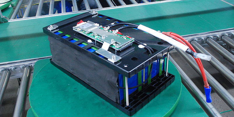
The Solution: Engineering a Custom Constraint System
Recognizing that manual alignment was insufficient for the client’s specific shell requirements, our engineering team pivoted to a Jig-Based Manufacturing Process.
-
Precision CNC-Milled Fixtures
We designed a custom assembly jig using high-stability, non-conductive materials (such as POM or Epoxy board).
- Zero-Tolerance Cavities: Each cell is seated into a CNC-milled pocket that compensates for the maximum allowable cell diameter while enforcing a strict outer boundary.
- Vertical Compression: The jig applies uniform lateral and vertical pressure, ensuring cells are perfectly planar before the first weld is made.
-
Specialized Nickel Strip Alignment
Instead of free-handing the nickel tabs, the new jig featured “guide slots” for the nickel strips. This ensures:
- Current Path Consistency: Every weld point is exactly where the simulation predicted.
- Structural Compactness: No “overhang” of nickel or solder, keeping the pack’s footprint within the 1mm tolerance threshold.
The Critical Role of Casing Integrity
Modern battery enclosures often utilize ultrasonic welding or high-precision interference fits. Once a shell is sealed, there is no “fixing” an internal error. Forcing a battery pack into a tight shell creates significant risks:
- Mechanical Stress: Constant pressure on cell walls can lead to internal micro-shorts over time.
- Thermal Expansion: Batteries naturally expand slightly during charge/discharge cycles. If the initial assembly does not account for this with precise tolerances, expansion can crack the casing or damage the Battery Management System (BMS).
Engineering Insights: Communication is Key to Precision
The most significant takeaway from this case is that Dimensional Specification is just as critical as Amp-Hour Capacity. For clients with high-precision requirements, we recommend the following protocol during the Request for Quote (RFQ) phase:
- Define “Critical-to-Quality” (CTQ) Dimensions: Don’t just provide the internal dimensions of your box. Define the Maximum Envelope Dimensions (MED) of the battery pack. Our engineers will then work backward to calculate the necessary jig offsets.
- Discuss Fixturing Early: If your project has a clearance of less than 2mmbetween the pack and the shell, a custom jig is mandatory. We discuss the cost-benefit analysis of jig fabrication upfront to ensure high yield rates.
- Tolerance Stack-up Analysis: We provide clients with a report that includes cell manufacturer tolerances, shrink-wrap thickness, nickel strip positioning variance, and jig precision.
Technical Summary: Why Choose Jig-Stabilized Manufacturing?
| Benefit | Description |
| Repeatability | Whether producing 10 units or 10,000, dimensions remain identical. |
| Safety | Eliminates mechanical friction between the pack and the enclosure. |
| Serviceability | Ensures the pack can be extracted for maintenance without damaging the shell. |
| Optimized Density | Reduces wasted space (“slop”), often allowing more capacity in the same volume. |
Conclusion
At our facility, we believe that “close enough” is not an engineering term. The failure of a pack to fit into its housing is not just a logistical delay—it is a failure of process control. By investing in custom jigs and rigorous fixture protocols, we ensure that our lithium solutions are as precise as the devices they power.
Are you working on a project with strict dimensional constraints? Contact our engineering team today to discuss your CAD requirements and how our custom fixturing process can guarantee a perfect fit.