Himax Electronics Battery Bolg

himax-electronics-manufacturing-headquarters-2

Introduction

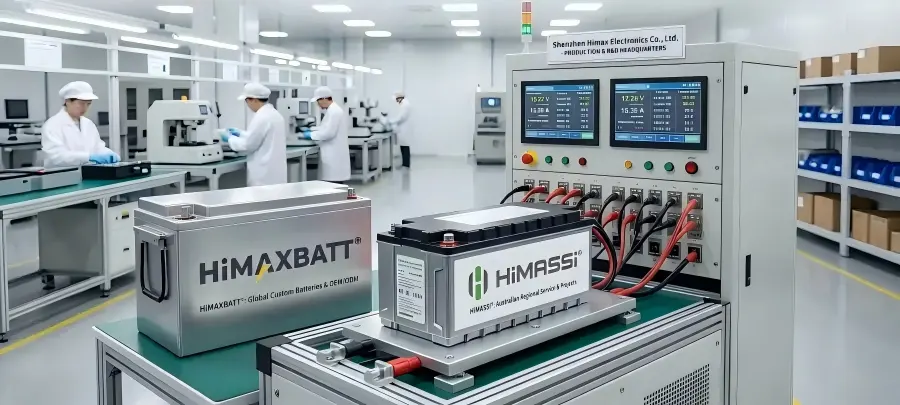
If you have visited different HIMAX websites or come across our battery products online, you may have seen several names: HIMAX Electronics, HiMAXBATT®, and HiMASSi®.

So, what is the relationship between them?

Shenzhen Himax Electronics Co., Ltd. is our company and manufacturing entity in Shenzhen, China, responsible for battery R&D, engineering, and production.

HiMAXBATT® is our global battery brand, focused on custom battery products and OEM/ODM battery solutions for customers worldwide.

HiMASSi® is the battery brand of our Australian subsidiary, Himax Electronics Pty Ltd, primarily serving customers in the Australian market.

Although these names serve different roles and markets, they are connected through the same broader battery business, engineering expertise, and manufacturing capabilities.

This article explains how HIMAX Electronics, HiMAXBATT®, and HiMASSi® are related, what each name represents, and where you may encounter them when working with us.

  1. HIMAX Electronics: Our Company and Manufacturing Entity

Shenzhen Himax Electronics Co., Ltd. is based in Shenzhen, China, and focuses on rechargeable battery R&D, engineering and manufacturing.

For us, a battery project usually starts with a piece of equipment rather than with a battery model.

Where will the battery be installed?What voltage does the equipment need?How much current does it draw during normal operation?Does it require higher current during startup?How long should it operate?How much space is available?What charging system will be used?What kind of working environment will the battery face?

The answers to these questions shape the battery design.

Depending on the project, our engineering work may involve:

  • Battery chemistry selection
  • Cell format selection
  • Series and parallel configuration
  • Voltage and capacity design
  • Continuous and peak current requirements
  • Battery dimensions and installation space
  • Connector and cable configuration
  • PCM or BMS protection
  • Charging requirements
  • Communication interfaces
  • Operating temperature
  • Enclosure design
  • Prototype development
  • Testing and production


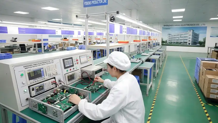
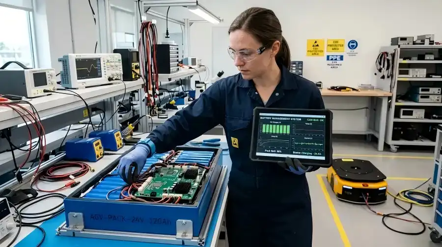
HIMAX Electronics engineer testing battery BMS circuit in cleanroom laboratory


This is why we see custom battery manufacturing as more than cell assembly.The battery needs to be designed around the equipment.

Our manufacturing and engineering capabilities cover several rechargeable battery technologies, including:

  • Lithium-ion Battery
  • LiFePO4 Battery
  • Lithium-Polymer Battery
  • Ni-MH Battery

From initial requirements and product design to sample development, testing and volume production, we work with each project according to its actual requirements.

  1. HiMAXBATT®: Our Global Battery Brand

HiMAXBATT® is the battery brand of Shenzhen Himax Electronics Co., Ltd., primarily serving customers in global markets.

We work with equipment manufacturers, product developers and industrial customers that need battery packs designed around a specific product or application.

Many projects start with a simple request:“We need a 24V battery.”Or:“We currently use a 10Ah battery and want something lighter.”

These are useful starting points, but they are rarely enough to define the right battery.

Imagine three different devices that all require a nominal 24V battery.One may operate continuously at a relatively low current.Another may drive a motor and require much higher current during startup.A third may have very limited internal space and require a specific battery shape and connector location.
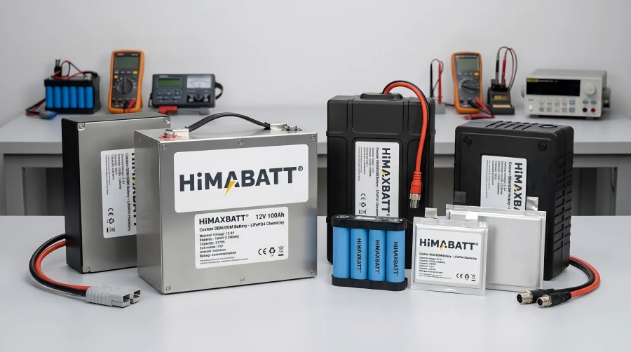
 

HiMAXBATT customized LiFePO4 and lithium battery packs with brand logo


All three are 24V applications, but the correct battery design for each can be completely different.That is why we do not look at voltage and capacity alone. We first understand the equipment and its operating conditions, then evaluate the cell chemistry, configuration, protection system and mechanical structure.

Our goal is not simply to provide a battery. It is to help develop a battery that works properly with the equipment it powers.

2.1 What Does HiMAXBATT® Provide?

HiMAXBATT® focuses on customized battery products and OEM/ODM battery solutions.

Depending on the project, a battery pack may be developed around requirements such as:

  • Cell chemistry
  • Cell format
  • Voltage
  • Capacity
  • Discharge current
  • Battery dimensions
  • Series and parallel configuration
  • Connectors and cables
  • Protection requirements
  • Charging method
  • Communication functions
  • Housing and mechanical structure

Different battery technologies can be selected according to the equipment and application.

LiFePO4 Battery

LiFePO4 batteries are often considered when stable operation, safety characteristics and long cycle life are important.

Typical applications include:

  • UPS
  • Golf carts
  • Electric wheelchairs
  • Low-speed electric vehicles
  • Marine auxiliary equipment
  • RV auxiliary power
  • Industrial equipment
  • Outdoor equipment

LiFePO4 is also commonly considered for lead-acid replacement projects.When replacing a lead-acid battery, however, matching the nominal voltage is only the beginning.The complete system may also need to be checked for:

  • Charging voltage
  • Charger compatibility
  • Peak current
  • Controller requirements
  • Battery compartment dimensions
  • Protection system
  • Operating temperature
  • Wiring and connectors

A successful lead-acid replacement is therefore not simply a change of battery chemistry. It is a matter of ensuring that the new battery works correctly with the existing equipment.

Lithium-ion Battery

Lithium-ion batteries offer a wide range of cell specifications and formats and are used in many portable and industrial products.Common cylindrical cell formats include 18650 and 21700.

Applications may include:

  • Security equipment
  • Portable industrial equipment
  • Communication equipment
  • Monitoring devices
  • Emergency equipment
  • Electronic equipment

The final battery configuration can be adjusted according to required voltage, capacity, discharge capability and available installation space.

Lithium-Polymer Battery

Lithium-polymer batteries use pouch cells and offer greater flexibility in terms of thickness and shape.This can be especially useful for products with:

  • Limited internal space
  • Thin housings
  • Irregular battery compartments
  • Tight weight constraints
  • Customized battery dimensions

Applications may include:

  • Portable medical equipment
  • Portable testing instruments
  • Handheld devices
  • Wearable electronics
  • Compact electronic equipment
  • Drones

For these applications, the battery often needs to be considered together with the mechanical design of the final product.

Ni-MH Battery

Ni-MH batteries remain relevant to certain industrial, electronic and replacement applications.

Typical applications include:

  • Emergency lighting
  • Measuring instruments
  • Industrial equipment
  • Communication equipment
  • Electronic devices
  • Replacement projects for traditional Ni-Cd battery systems

The charging and protection approach for Ni-MH batteries is different from that used with lithium battery systems.For this reason, the battery configuration and charging requirements should be evaluated according to the equipment rather than simply applying a lithium-style BMS architecture.

2.2 Where Are HiMAXBATT® Battery Solutions Used?

Because every piece of equipment has different power requirements, custom battery solutions can serve a wide range of applications.

Medical Equipment

Medical equipment may require a combination of stable power delivery, reliable operation, compact dimensions and suitable operating time.

Applications may include:

  • Patient monitoring equipment
  • Portable diagnostic equipment
  • Infusion equipment
  • Rehabilitation equipment
  • Portable respiratory equipment
  • Mobile medical terminals
  • Emergency medical equipment

Industrial Equipment

Industrial equipment may need to operate for long periods and remain stable under demanding conditions.

Applications may include:

  • Industrial automation equipment
  • Inspection instruments
  • Measurement equipment
  • Remote monitoring equipment
  • Industrial control terminals
  • Portable industrial equipment

UPS and Backup Power

Battery packs used in UPS and backup-power equipment may need to balance capacity, discharge capability, operating time, charging requirements and available space.

Golf Carts and Electric Mobility

Golf carts and other low-speed electric vehicles may require repeated cycling as well as relatively high current during startup and acceleration.

For lead-acid replacement projects, it is important to evaluate the battery together with:

  • System voltage
  • Peak current
  • Continuous current
  • Charger compatibility
  • Battery compartment
  • Vehicle controller
  • Protection system

Marine and Outdoor Equipment

Marine and outdoor applications can place additional requirements on:

  • Weight
  • Space
  • Vibration
  • Temperature
  • Operating environment
  • Long operating periods

The final battery design should reflect the actual equipment and its working conditions.

  1. HiMASSi®: Our Battery Brand for the Australian Market

HiMASSi® is a battery brand of our Australian subsidiary, Himax Electronics Pty Ltd, and primarily serves the Australian market.

HiMASSi® is supported by the battery R&D, engineering and manufacturing capabilities of the Shenzhen organization.

Depending on the project, the Australian business can support:

  • Custom battery requirements
  • Product selection
  • OEM/ODM projects
  • Technical communication
  • Sample coordination
  • Production coordination


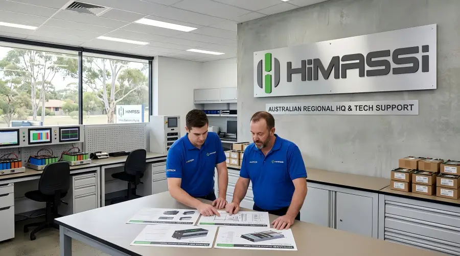
HiMASSi regional office and battery technical support center in Australia


The main distinction is the market served:

  • HiMAXBATT®→ global market
  • HiMASSi®→ primarily Australian market

Both are connected to the broader battery engineering and manufacturing capabilities of HIMAX Electronics.

  1. HIMAX Electronics, HiMAXBATT® and HiMASSi® at a Glance
Name What it represents Main role Main market
Shenzhen Himax Electronics Co., Ltd. Company and manufacturing entity Battery R&D, engineering and production Global
HiMAXBATT® Battery brand of Shenzhen Himax Electronics Custom battery products and OEM/ODM solutions Global
HiMASSi® Battery brand of Himax Electronics Pty Ltd Battery products and project support Primarily Australia

The simplest way to remember the relationship is:

  • HIMAX Electronicsis our company and manufacturing entity.
  • HiMAXBATT®is our global battery brand.
  • HiMASSi®is our battery brand primarily serving Australia.

If you come across different names in our materials, they are not unrelated businesses. They simply represent different parts of our company and market structure.

  1. Why You May See Different HIMAX Names

Depending on where you first encounter us, you may see the company name, the global battery brand or the Australian-market battery brand.

For example:

  • Company and manufacturing information may appear underHIMAX Electronics.
  • Global battery products and customized battery solutions may appear underHiMAXBATT®.
  • Australian-market battery products and projects may appear underHiMASSi®.

This is why the name you see may vary from one website or project document to another.The important point is that the underlying battery R&D, engineering and manufacturing capabilities are connected.

  1. Which HIMAX Website Should You Visit?

Each of our three websites has a different focus.

himaxelectronics.com

Our company and manufacturer websiteHere, you can learn more about:

  • Our company
  • Battery R&D
  • Engineering capabilities
  • Manufacturing
  • OEM/ODM manufacturing
  • Product capabilities

If you want to understand Shenzhen Himax Electronics Co., Ltd. as a battery manufacturer, this is the best place to start.

himaxbatt.com

The HiMAXBATT® global battery brand websiteHere, you can explore:

  • Custom batteries
  • Battery products
  • Battery applications
  • OEM/ODM services
  • Technical information

If you are looking for custom battery solutions for global projects, this is the main HiMAXBATT® website.

himaxelec.com.au

Our Australian market websiteThis website is associated with Himax Electronics Pty Ltd and the HiMASSi® battery brand and focuses on the Australian market.If your project is primarily based in Australia, you can find relevant product and project information here.

  1. Why the Company Behind the Battery Matters

A battery pack may look like a finished product, but successful battery development often involves much more than assembling cells.

A custom project may begin with:Equipment requirementsand continue through:Battery chemistry → Cell configuration → Electrical design → Protection → Mechanical integration → Prototype → Testingbefore reaching:Volume production and ongoing supply.

For OEM and ODM projects, this process matters even more because the battery may become an integrated part of the final equipment.

That is why we always look beyond the battery label and ask a more important question:Will this battery work properly with the equipment?

A good battery is not simply a pack with the right voltage and capacity.It is a battery designed around the equipment’s real requirements.

Conclusion

If you are new to HIMAX, the relationship between the three names can be remembered quite simply:

  • Shenzhen Himax Electronics Co., Ltd.Our company and manufacturing entity, responsible for battery R&D, engineering and production.
  • HiMAXBATT®Our global battery brand, focused on custom battery products and OEM/ODM battery solutions.
  • HiMASSi®Our battery brand primarily serving the Australian market through Himax Electronics Pty Ltd.

Behind these names are connected battery R&D, engineering and manufacturing capabilities.

And when you are developing a custom battery, you do not need to begin with a specific battery model.It is often more useful to start with a few simple questions:

  • What voltage does the equipment need?
  • How much current does it require?
  • Does it need higher peak current at startup?
  • How long should it operate?
  • How much space is available for the battery?
  • What charger will be used?
  • What kind of environment will it work in?

Once these requirements are clear, it becomes much easier to evaluate the right battery chemistry, cell configuration, protection system and mechanical design.

A battery is not simply a group of cells. The right battery is one that is designed to work with the equipment it powers.

Commercial solar street light system powered by LiFePO4 battery pack at sunset

Solar Street Light Battery Solutions: LiFePO4 Battery Capacity, Cycle Life, and Outdoor Performance

Commercial Disclosure: The HiMAXBATT Editorial Team brings together expertise in lithium battery manufacturing, battery engineering, power systems, and global application support to provide practical, technically informed content for businesses and industry professionals. Our content covers lithium-ion and LiFePO4 batteries, custom battery packs, BMS technology, charging solutions, battery selection, industrial applications, product updates, and HiMAXBATT news. All content reflects HiMAXBATT’s official editorial perspective and our commitment to delivering safe, reliable, and application-focused lithium battery solutions to customers worldwide.

Key Takeaways

  • Solar street light battery capacity should be calculated based on the light’s actual power consumption, daily lighting hours, required backup days, depth of discharge, and overall system efficiency.
  • Ah alone does not indicate how much energy a battery stores. Battery voltage and Wh should also be considered when comparing battery options.
  • The cycle life of a LiFePO4 battery is affected by depth of discharge, temperature, charge and discharge rates, and cell consistency.
  • High temperatures can accelerate battery aging, while low temperatures may reduce usable capacity and limit charging capability.
  • The solar panel, controller, LED light, and battery must be properly matched. Simply increasing battery capacity will not necessarily solve an energy shortage.
  • Outdoor battery designs should account for water and dust protection, condensation, corrosion, vibration, and theft.
  • The BMS should provide overcharge, over-discharge, overcurrent, short-circuit, and temperature protection while working properly with the solar charge controller.
  • Project buyers should compare total life-cycle costs rather than focusing only on the battery’s upfront price.

Introduction

Solar street lights use energy collected during the day to provide lighting at night without the need for long cable runs. They are widely used on urban and rural roads, in parking lots, industrial parks, parks, campuses, and remote areas. As the core energy storage component, the battery directly affects nightly operating time, backup runtime during consecutive cloudy or rainy days, failure rates, and long-term maintenance costs.

Among solar street light battery solutions, lithium iron phosphate (LiFePO4) batteries have become a common choice for many new projects because of their relatively long cycle life, good thermal stability, and efficient energy utilization. However, selecting a lithium battery for a solar street light involves more than choosing a capacity. The complete system should be designed around the LED power demand, lighting schedule, local solar conditions, controller parameters, and outdoor operating environment.

Why Are LiFePO4 Batteries Well Suited for Solar Street Lights?

Traditional solar street lights often use lead-acid or gel batteries. These are mature battery technologies with relatively low upfront costs, but they are typically heavier and bulkier, while their deep-cycle performance and energy utilization may not meet the requirements of some long-term outdoor lighting projects.

LiFePO4 batteries for solar street lights typically offer several advantages:

  • Relatively long cycle life for applications involving daily charging and discharging;
  • Good thermal stability for outdoor applications;
  • A relatively stable discharge voltage plateau;
  • High charging efficiency for better use of available solar energy;
  • Generally lower weight and smaller size than lead-acid batteries for the same usable energy;
  • Low self-discharge;
  • Relatively low routine maintenance requirements;
  • Compatibility with smart BMS monitoring;
  • Suitability for both all-in-one and split-type solar street light designs.

However, using LiFePO4 batteries does not eliminate the need for proper system matching. Insufficient solar panel output, incorrect charging parameters, prolonged exposure to high battery-compartment temperatures, or poor water protection can still result in insufficient runtime and premature battery degradation.

How Do You Calculate Solar Street Light Battery Capacity?

Battery capacity should be calculated based on daily energy consumption, required backup days, depth of discharge (DoD), and system efficiency.

Daily Energy Consumption (Wh) = Actual Light Power (W) × Lighting Time (h)

If scheduled dimming is used, calculate the energy consumption for each period separately. For example, consider a 60W solar street light operating for 12 hours per night: 100% brightness for the first 4 hours, 60% for the next 4 hours, and 30% for the final 4 hours:

60 × 4 + 60 × 60% × 4 + 60 × 30% × 4 = 456Wh

Next, estimate the required battery energy:

Recommended Battery Energy (Wh) = Daily Energy Consumption × Backup Days ÷ Allowable Depth of Discharge ÷ System Efficiency

If the system needs to support three nights, with an 80% DoD and 90% overall system efficiency:

456 × 3 ÷ 0.8 ÷ 0.9 ≈ 1900Wh

For a 12.8V LiFePO4 battery:

1900 ÷ 12.8 ≈ 148Ah

Under these example conditions, a 12.8V 150Ah battery or a custom battery solution with an appropriate design margin could be considered as a starting point. Final sizing should also account for solar irradiance during the worst month, temperature, battery aging, and the controller’s own power consumption.

What’s the Difference Between Ah and Wh?

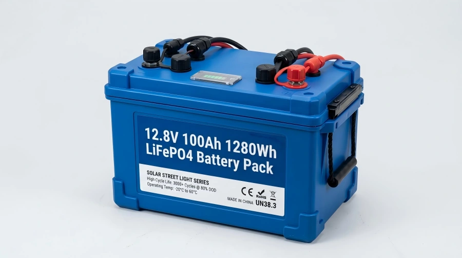
Ah stands for amp-hours, while Wh stands for watt-hours. Solar street lights may use 12V, 24V, or other voltage platforms, so comparing Ah alone can be misleading.Commercial 12.8V 100Ah 1280Wh LiFePO4 lithium battery pack for solar street lights


Battery Energy (Wh) = Nominal Voltage (V) × Battery Capacity (Ah)

LiFePO4 Battery Specification Theoretical Energy Selection Considerations
12.8V 50Ah 640Wh Suitable for lower-power systems or shorter lighting periods
12.8V 100Ah 1280Wh Common option for small to medium solar street light systems
12.8V 150Ah 1920Wh Can support longer lighting periods or additional backup time
25.6V 50Ah 1280Wh Similar theoretical energy to a 12.8V 100Ah battery
25.6V 100Ah 2560Wh Suitable for higher-power or longer-runtime requirements

At the same 50Ah capacity, a 25.6V battery has approximately twice the theoretical energy of a 12.8V battery. For this reason, solar street light battery selection should consider V, Ah, and Wh together.

What Factors Affect Actual Battery Capacity Requirements?

Actual Input Power of the Light

Some products are labeled according to LED chip power, peak power, or equivalent lighting power, which may not be the same as the actual input power of the complete light. Battery calculations should use measured input power at each brightness setting.

Nightly Lighting Time

Winter nights are longer. If a system is designed only around summer lighting hours, it may shut off too early during winter. Battery sizing should be based on the longest required nightly operating time.

Consecutive Cloudy or Rainy Days

The required number of backup days is an important factor in battery sizing. Rainy seasons and solar irradiance vary significantly by location, so a single backup-day assumption should not be applied to every project.

Smart Dimming Strategy

Reducing brightness during periods of low traffic or using motion detection for pedestrians and vehicles can significantly reduce daily energy consumption. However, the dimming strategy still needs to meet roadway lighting and safety requirements.

Battery Aging Margin

The usable capacity of a LiFePO4 battery gradually decreases over long-term cycling. If the system only meets its requirements when the battery is new, it may no longer provide sufficient backup during poor weather later in its service life. Battery sizing should therefore account for end-of-life capacity.

Ambient Temperature

Low temperatures can reduce usable battery capacity and output capability, while high temperatures accelerate battery aging. Capacity calculations should be adjusted according to the actual temperature range at the project location.

How Should the Solar Panel Be Matched to a LiFePO4 Battery?


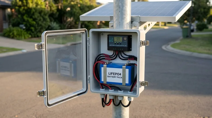
Solar street light IP67 enclosure featuring MPPT controller and LiFePO4 battery pack


The battery stores energy, while the solar panel generates it. If the solar panel consistently produces less energy each day than the street light consumes, even a large battery will eventually become depleted.

Daily solar energy generation can be roughly estimated using:

Daily Energy Generation (Wh) ≈ Solar Panel Power (W) × Peak Sun Hours (h) × System Efficiency

For example, if a 200W solar panel receives 4 peak sun hours per day and overall system efficiency is estimated at 75%:

200 × 4 × 0.75 = 600Wh

If the street light consumes 456Wh per day, the system theoretically has some charging margin. However, after several cloudy or rainy days, the solar panel must supply enough energy for that night’s lighting while also replenishing energy previously drawn from the battery. Solar panel capacity should therefore also be designed around the desired recovery time.

System Component Key Selection Parameters Common Issues
Solar Panel Power, operating voltage, installation angle Insufficient output or shading
LiFePO4 Battery Voltage, Wh capacity, temperature range Insufficient capacity or low-temperature charging limitations
Solar Charge Controller Charging parameters, efficiency, maximum current Charging profile does not match the battery
LED Light Actual power, luminous efficacy, dimming strategy Rated power differs from actual consumption
Cables and Connectors Current capacity, voltage drop, water resistance Power loss, corrosion, or poor connections
Energy Losses Conversion efficiency of the battery, controller, and wiring
Recycling and Disposal Cost Transportation, recycling, and compliant disposal of used batteries

How Many Cycles Can a LiFePO4 Solar Street Light Battery Last?

Cycle life should not be compared as a standalone number without considering the test conditions. A manufacturer’s stated cycle count typically applies under specified temperature, charge/discharge rate, depth of discharge, and capacity-retention conditions.

Factors affecting solar street light battery cycle life include:

  • Daily depth of discharge;
  • Charge cutoff voltage;
  • Charge and discharge rates;
  • Long-term operating temperature;
  • Cell quality and consistency;
  • BMS protection and balancing performance;
  • Matching between the solar panel and load;
  • How long the battery remains at a high state of charge;
  • Frequency of deep discharge during extended cloudy or rainy weather;
  • Battery enclosure protection and thermal management.

When comparing cycle-life specifications from different suppliers, check the test temperature, depth of discharge, charge/discharge current, and capacity-retention criteria. Cycle counts measured under different conditions should not be compared directly, even if the published numbers appear identical.

How Does High Temperature Affect Solar Street Light Batteries?

During summer, direct sunlight can cause temperatures inside the light fixture, behind the solar panel, or inside a sealed battery enclosure to rise well above ambient temperature. Prolonged exposure to high temperatures may:

  • Accelerate battery capacity degradation;
  • Increase heat buildup in the battery and BMS;
  • Cause high-temperature protection to trigger more frequently;
  • Shorten the service life of seals and connectors;
  • Accelerate aging of insulation materials and electronic components;
  • Reduce the long-term reliability of the complete system.

Outdoor battery systems can manage temperature through shading, thermal insulation, separation from heat sources, appropriate placement of temperature sensors, and optimized charging strategies. A fully sealed enclosure may improve water protection but can also make heat dissipation more difficult, so environmental protection and thermal management need to be considered together.

Can LiFePO4 Batteries Operate Normally in Cold Weather?

Low temperatures can reduce the usable capacity and discharge capability of LiFePO4 batteries, while charging performance is often affected even more significantly. Charging at relatively high current when the battery temperature is too low may damage the cells.

For solar street light batteries used in cold climates, consider:

  • Low-temperature charging protection in the BMS;
  • Temperature-based charging current limits;
  • Cells designed for better low-temperature performance;
  • Thermal insulation;
  • Self-heating when necessary;
  • Additional temperature margin in winter capacity calculations;
  • Avoiding prolonged storage or operation at a low state of charge.

Self-heating also consumes energy, so heater power, activation temperature, and operating duration should be included in the overall solar street light energy budget.

What Should You Consider for Outdoor Water, Dust, and Condensation Protection?

Solar street lights are continuously exposed to rain, dust, UV radiation, salt spray, and day-to-night temperature changes. Even when the battery is not directly exposed to rain, moisture may enter the battery compartment through cable entries, enclosure seams, or pressure changes caused by temperature fluctuations.

The mechanical design should consider:

  • Water and dust resistance of the enclosure;
  • Sealing around connectors and cable entries;
  • UV resistance of enclosure materials;
  • Corrosion protection for metal components;
  • Condensation management and pressure equalization;
  • Electrical insulation for cells and the BMS;
  • Harness retention and abrasion protection;
  • Anti-theft design;
  • Accessibility for inspection and replacement;
  • Vibration resistance during transportation and installation.

A higher enclosure protection rating is not automatically better in every application. Excessive sealing can create challenges for heat dissipation and pressure equalization. The enclosure should be designed according to the battery’s installation location and actual environmental risks.

How Do You Choose Between Buried, Pole-Mounted, and Integrated Batteries?

Installation Method Main Advantages Key Considerations
Buried Relatively stable temperature and clean appearance Water resistance, moisture protection, drainage, and maintenance access
Inside the Pole Better theft protection and no additional external space required Available dimensions, heat dissipation, and maintenance access
Separate Battery Box Easier inspection and replacement Sun exposure, water resistance, theft protection, and corrosion resistance
Integrated into the Light Fixture Compact design and relatively easy installation High temperature, weight, available space, and heat dissipation
Behind the Solar Panel Shorter wiring and high system integration High temperatures caused by direct sunlight


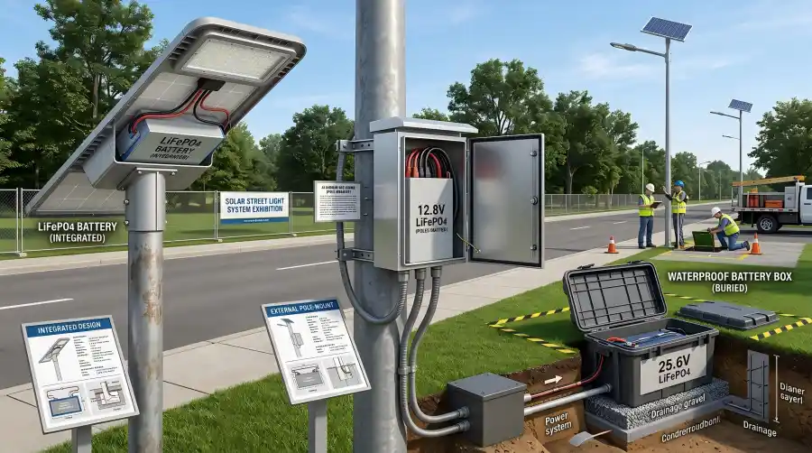
Comparison of integrated, pole-mounted, and buried solar street light battery installations


In hot climates, integrated batteries and batteries installed behind solar panels should be validated under worst-case summer temperature conditions. In areas prone to standing water, buried battery enclosures require more rigorous sealing and drainage design.

What Does a BMS Do in a Solar Street Light Battery?

A BMS, or battery management system, is an important part of a LiFePO4 solar street light battery. Common functions include:

  • Individual cell and total pack voltage monitoring;
  • Charge and discharge current monitoring;
  • Overcharge and over-discharge protection;
  • Overcurrent and external short-circuit protection;
  • High- and low-temperature protection;
  • Cell balancing;
  • State-of-charge (SOC) estimation;
  • Fault logging;
  • Status communication when required.

Solar panel output changes continuously with weather conditions, so the BMS needs to work properly with the solar charge controller. If the BMS disconnects charging or discharging and the controller does not have appropriate recovery logic, the battery may fail to resume charging or the street light may not turn on as expected.

How Do You Choose Between PWM and MPPT Controllers?

PWM controllers have a relatively simple design and can be suitable for lower-power, cost-sensitive systems where the solar panel and battery voltage are properly matched. MPPT controllers track the solar panel’s maximum power point and can improve solar energy utilization under certain irradiance and temperature conditions, although they typically add cost and system complexity.

Regardless of controller type, confirm:

  • Whether it supports LiFePO4 batteries;
  • Whether the charge cutoff voltage can be set correctly;
  • Whether the maximum charging current meets system requirements;
  • The controller’s own standby power consumption;
  • Whether temperature sensing is available;
  • Whether light control and scheduled dimming are supported;
  • Low-voltage protection and recovery thresholds;
  • Compatibility between controller and BMS protection logic.

Charging parameters intended for lead-acid batteries should not be applied directly to LiFePO4 batteries without confirming compatibility.

How Can You Reduce the Total Life-Cycle Cost of Solar Street Lights?

The initial purchase price is only one part of the total project cost. For large roadway lighting projects, battery replacement may involve significant costs for vehicles, labor, working at height, and traffic management.

Cost Category What to Evaluate
Initial Purchase Cost Battery, solar panel, controller, and installation hardware
Installation Cost Transportation, foundation work, working at height, and commissioning
Routine Maintenance Cost Inspection, cleaning, troubleshooting, and spare parts
Battery Replacement Cost Replacement battery, labor, vehicles, and traffic management
Lighting Downtime Cost Safety risks, complaints, and project service costs
Energy Losses Conversion efficiency of the battery, controller, and wiring
Recycling and Disposal Cost Transportation, recycling, and compliant disposal of used batteries

A high-quality LiFePO4 solar street light battery may have a higher upfront price, but if it reduces replacement frequency, maintenance requirements, and lighting failures, it may offer a lower total life-cycle cost.

Solar Street Light Battery Selection Checklist

When requesting a custom battery solution from a battery manufacturer, prepare the following information:

  1. Actual LED light power;
  2. Nightly lighting duration;
  3. Scheduled or motion-based dimming strategy;
  4. Project location and solar irradiance data;
  5. Required number of consecutive backup days;
  6. Solar panel power, quantity, and operating voltage;
  7. Controller model, maximum current, and charging parameters;
  8. Battery system voltage and target capacity;
  9. Maximum charge and discharge current;
  10. Minimum and maximum ambient temperatures;
  11. Battery installation location and available space;
  12. Water, dust, theft, and corrosion protection requirements;
  13. Low-temperature heating or remote communication requirements;
  14. Target cycle life and warranty requirements;
  15. Transportation, testing, and target-market requirements;
  16. Project quantity and delivery schedule.

Frequently Asked Questions (FAQ)

What Battery Capacity Does a Solar Street Light Need?

Battery capacity should be calculated based on the light’s actual power consumption, lighting duration, dimming strategy, required backup days, depth of discharge, system efficiency, and ambient temperature. The light’s rated wattage alone is generally not enough to determine the required battery capacity accurately.

How Long Can a 12.8V 100Ah Battery Power a Street Light?

A 12.8V 100Ah battery has a theoretical energy capacity of approximately 1280Wh. If 80% is considered usable, that provides about 1024Wh. With an average light power consumption of 40W, the theoretical runtime would be approximately 25.6 hours. Actual runtime will also depend on temperature, wiring losses, and battery condition.

Is a 12V or 24V Battery Better for a Solar Street Light?

Both system voltages have suitable applications. Lower-power street lights commonly use 12V-class systems, while higher-power equipment may benefit from a 24V-class system to reduce operating current at the same power level. The final choice should be based on the LED light, controller, and solar panel as a complete system.

Why Does a Solar Street Light Turn Off Early During Cloudy or Rainy Weather?

Possible causes include insufficient battery capacity, undersized solar panels, panel shading, reduced winter sunlight, battery aging, incorrect controller settings, excessive wiring losses, or an unsuitable dimming strategy.

Can a LiFePO4 Solar Street Light Battery Be Charged Below Freezing?

The minimum allowable charging temperature and charging current should be determined from the cell and battery specifications. Conventional LiFePO4 batteries generally require charging to be limited or stopped at low temperatures. For cold-climate projects, low-temperature protection, insulation, or self-heating can be considered.

How Often Should a Solar Street Light Battery Be Replaced?

Replacement intervals depend on ambient temperature, depth of discharge, charge and discharge rates, cell quality, and how well the solar system is matched. Battery condition should not be judged by age alone. Capacity, internal resistance, runtime, and fault history should also be evaluated.

Does a Larger Solar Panel Charge the Battery Faster?

When sunlight, controller capacity, and battery charging limits allow, a higher-power solar panel can generally provide greater charging capability. However, increasing panel power may not produce the expected result if the controller limits current, low-temperature protection is active, or the panel is shaded.

Is It Suitable to Install the Battery Under the Solar Panel?

This configuration can provide a compact design, but temperatures behind the solar panel may become high. Battery enclosure temperatures should be validated under strong summer sunlight, with appropriate shading, insulation, heat dissipation, and water protection incorporated into the design.

Does a Solar Street Light Battery Need Communication Capability?

Communication is not always necessary for small standalone street lights. In larger projects, communication can provide access to voltage, SOC, temperature, and fault information, supporting remote maintenance and reducing the need for on-site troubleshooting.

Why Can a Newly Installed Solar Street Light Still Have a Low Battery?

Possible causes include the battery not being fully charged before installation, incorrect solar panel wiring or orientation, incompatible controller settings, panel shading, or actual light power consumption exceeding the design assumptions. The complete system should be inspected rather than assuming the battery itself is the problem.

Can Increasing Battery Capacity Solve Runtime Problems During Consecutive Cloudy or Rainy Days?

Increasing capacity can provide more stored energy, but if the solar panel cannot generate enough energy, the battery may not recharge adequately after poor weather. A better approach is to evaluate battery capacity, solar panel power, dimming strategy, and expected energy recovery time together.

How Can You Extend the Life of a LiFePO4 Solar Street Light Battery?

Avoid prolonged exposure to high temperatures, frequent deep discharge, and incompatible charging parameters, while ensuring the solar panel provides sufficient energy margin. A reliable BMS, appropriate battery enclosure design, and suitable maintenance plan can also help extend battery service life.

About Himax Electronics

Himax Electronics specializes in custom battery and power solutions for complex applications worldwide. For solar street lights, outdoor lighting, remote monitoring systems, and other off-grid equipment, we can develop application-specific LiFePO4 battery packs, power supplies, chargers, control interfaces, and related accessories based on system voltage, LED power requirements, backup days, solar panel specifications, installation space, and operating temperature.

From cell selection, battery capacity calculations, BMS protection, and mechanical design to low-temperature heating, wiring connections, and solar charging compatibility, Himax Electronics works with customers to develop energy storage systems designed for stable operation, durability, and easier system integration.

Blog Thumbnail Custom Medical Battery North America Himax Electronics

better understand battery technologies and make informed decisions based on their specific application requirements. All content reflects the official editorial perspective of Himax Electronics and our commitment to providing reliable, flexible, and professional custom battery and power solutions for complex applications worldwide.

Key Takeaways

  • Developing a custom battery for a portable medical device is not as simple as selecting cells and combining them to reach a target capacity.The battery system should be designed around the device’s operating voltage, average and peak power demand, target runtime, available installation space, charging method, and operating environment.
  • Cell selection should consider chemistry, energy density, cycle life, discharge capability, temperature range, and supply continuity, rather than focusing only on capacity or unit cost.
  • The BMS, connectors, communication protocols, and fuel-gauging functions are important parts of how the battery pack works with the medical device, especially for products that require battery-level display, low-battery alerts, or battery identification.
  • Battery safety testing, transportation testing, and medical device system-level validation are different stages.For example, UN 38.3 primarily addresses lithium battery transportation requirements and does not, by itself, demonstrate that a battery is suitable for a specific medical device. Pipeline and Hazardous Materials Safety Administration
  • Custom battery development should take future mass production and change control into account early in the project.If cells, the BMS, connectors, or other critical materials are changed, the impact on previous validation results and the final device should be evaluated.
  • For medical device manufacturers, OEMs, and product development teams, providing complete project requirements early can help reduce redesign work caused by mismatches in dimensions, electrical interfaces, charging systems, or compliance requirements.

Why Do Portable Medical Devices Need Batteries Designed Around the Complete System?

Portable patient monitors, infusion pumps, portable respiratory equipment, diagnostic instruments, and other mobile medical devices may rely on batteries to operate away from a fixed power source.

However, battery requirements can vary significantly from one device to another.

Some devices need to operate for long periods at a relatively stable power level. Others may experience short bursts of higher load during startup, pump operation, or certain functions. Some devices also need to read battery data in real time, such as remaining capacity, temperature, or cycle count.

For medical device manufacturers, a better starting point for custom battery development is usually not:

“We need a 5000mAh lithium battery.”

Instead, the project should begin by answering:

“How much energy and power does the device need under actual operating conditions, and how should the battery work with the complete system?”

This is one of the first questions to address when moving from standard cells to a Custom Medical Device Battery Pack.

What Information Should You Provide to a Battery Manufacturer Before Development Begins?


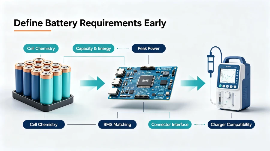
Blog Inline Battery Design Process Medical Devices


A B2B custom battery project usually starts with defining the device requirements. The more complete the information provided by the product development team, the easier it is for the battery manufacturer to determine whether the proposed cells, series/parallel configuration, BMS, and mechanical design are appropriate.

Item Information to Provide Impact on Battery Design
Operating Voltage Nominal voltage, acceptable input range Number of cells in series, voltage platform
Power Consumption Average power, peak power Capacity, cell discharge capability, BMS
Target Runtime For example, 2 hours, 4 hours, or a specific duty cycle Wh and Ah requirements
Installation Space Length, width, height, and mechanical constraints Cell format, layout, enclosure design
Weight Requirement Allowable battery weight range Cell chemistry and capacity configuration
Charging Method Charging voltage, current, charging interface Charging strategy and protection design
Output Interface Connector model, polarity, pin definition Wire harness and connector design
Communication Requirements SMBus, I²C, UART, or other protocols Smart BMS and software development
Operating Environment Temperature, humidity, vibration, and other conditions Cell selection, mechanical design, validation plan
Target Market United States, European Union, or other regions Compliance and testing plan

For replacement battery projects involving existing devices, the original battery specifications, device input requirements, and charging system information should also be provided. Two batteries should not be considered interchangeable simply because they have the same nominal voltage and capacity.

Step 1: How Do You Select the Right Battery Cells?

Battery Chemistry Is About More Than Energy Density

Common rechargeable battery options for portable medical devices may include lithium-ion, lithium-polymer, LiFePO4, and NiMH chemistries. The appropriate choice depends on the specific device requirements.

For example, compact portable devices may place greater emphasis on size and weight. Devices expected to undergo frequent charge and discharge cycles may place greater emphasis on cycle performance. Some applications may also require careful consideration of discharge performance at specific temperatures.

Cell selection can therefore be evaluated across several dimensions:

Evaluation Factor Questions to Consider
Voltage Platform Does it match the device input requirements and power architecture?
Energy Density Can the target Wh be achieved within the available space?
Discharge Capability Can the cell support both continuous and peak loads?
Cycle Performance Does it meet the expected usage and maintenance cycle?
Temperature Performance How does it perform during charging and discharging in the target environment?
Size and Format Is a cylindrical, prismatic, or pouch cell structure more suitable?
Consistency How will capacity, internal resistance, and other parameters be controlled in mass production?
Supply Continuity Is the cell suitable for long-term product lifecycle management?

For medical device OEM projects, long-term cell availability is also worth considering. If a product is expected to remain on the market for several years, changing the cell model later may require a reassessment of electrical performance, safety, and whether previous validation results still apply.

Step 2: How Should Capacity and Runtime Be Determined?

Medical device battery capacity should not be evaluated by mAh alone.

Wh is generally more useful when calculating energy requirements:

Nominal Energy (Wh) ≈ Nominal Voltage (V) × Rated Capacity (Ah)

For example, a 14.8V, 5Ah battery pack has a nominal energy of approximately:

14.8 × 5 = 74Wh

However, 74Wh does not mean that the device will necessarily be able to use the full 74Wh.

Actual usable energy can be affected by discharge cutoff voltage, conversion efficiency, temperature, battery aging, device operating modes, and the design margin built into the system.

During custom development, a practical starting point is:

Average Device Power Consumption × Target Operating Time

This provides a baseline energy requirement, which can then be adjusted based on real-world testing and the required design margin.

For devices with widely varying power consumption, different operating states should also be tested, including startup, standby, normal operation, wireless communication, and specific functional modes, rather than relying on a single average power figure.

Step 3: Why Does Peak Current Matter?

Capacity answers the question, “How much energy can the battery store?”

Power delivery answers a different question: “Can the battery deliver enough power when the device needs it?”

These are not the same issue.

For example, some devices with pumps, motors, heating elements, or other dynamic loads may draw significantly more current during certain operating stages than during normal operation.

Even if the cells store enough energy, problems can still occur if the cells, nickel strips, wiring, connectors, or BMS are not rated for the required current. Possible issues include:

  • Significant voltage drop at the battery terminals;
  • BMS overcurrent protection being triggered;
  • Increased temperature at connection points;
  • Low-battery alerts appearing on the device;
  • Certain loads failing to start properly.

For this reason, specifications for a custom medical device battery should define both Continuous Current and Peak Current, along with the peak duration and test conditions.

Step 4: How Should the BMS Work with the Medical Device?

A BMS, or Battery Management System, is more than just a protection board.

Depending on the battery pack design, the BMS may monitor voltage, current, and temperature while also providing protection against overcharge, over-discharge, overcurrent, and short circuits. Smart battery systems may also require state-of-charge estimation, data logging, and communication functions.

For portable medical devices, one particularly important question is:

Does the BMS protection logic match the device’s actual load profile?

For example, if a device draws a short burst of high current at startup but the BMS overcurrent threshold or delay time was not designed with that behavior in mind, normal startup could unintentionally trigger protection.

BMS parameters therefore should not be defined independently of the complete device load.

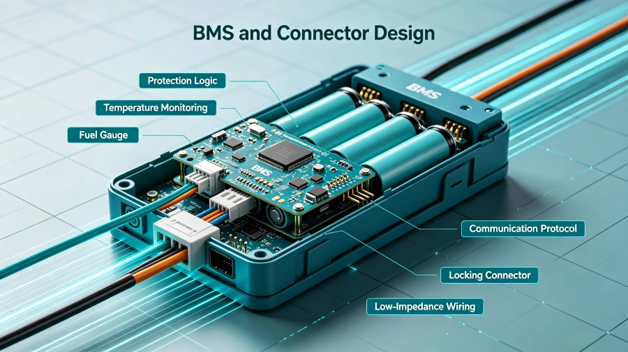
Step 5: Why Should Connectors and Communication Protocols Be Defined Early?

In some custom battery projects, customers first determine the cells and capacity, then wait until the battery design is nearly complete before confirming the connector.

This approach can increase the risk of rework.

A medical device battery interface may include more than positive and negative terminals. It may also support:

NTC temperature sensing, ID identification, SOC data, clock/data communication, and other control signals.

If the device uses a smart battery system, the communication protocol, data format, alarm logic, and the way the device reads remaining battery capacity should also be confirmed early in the development process.

The connector itself may need to meet requirements related to current rating, mating-cycle life, locking mechanism, reverse-polarity prevention, and installation space.

For this reason, Connector + Pinout + Communication Protocol should be included in the technical specification early in the custom battery development process, rather than treated as an accessory decision at the end.


Blog Inline Bms Connector Interface Medical Battery


Step 6: Why Should the Charger and Battery Be Considered Together?

Battery pack design is directly related to the charging system.

Different cell chemistries, series configurations, and BMS designs may require different charging voltages, currents, and control strategies. If the device includes an internal charging circuit, the compatibility between that charging system and the custom battery pack needs to be confirmed.

The FDA’s safety guidance for charging medical devices also advises users to follow the device manufacturer’s instructions and use the specified charging accessories. Incompatible third-party chargers may create risks such as overheating, sparks, or fire. U.S. Food and Drug Administration

For new OEM device development, the battery manufacturer and the device power-system design team should therefore confirm the complete power chain early:

Battery → BMS → Charging Circuit → Adapter/Power Supply → Device

The system should be considered as a whole rather than designing each component separately and trying to combine them later.

Step 7: How Should Safety, Transportation, and Medical Device Compliance Be Understood?

This is an area where misunderstandings can easily occur in custom medical device battery projects.

A battery passing a particular test does not mean that the medical device using that battery automatically meets all requirements for its target market.

Different standards and tests address different aspects of the product:

Standard / Testing Area Primary Focus What to Consider in the Project
UN 38.3 Lithium battery transportation testing Does not equal certification of the complete medical device
IEC 62133-2 Safety of portable sealed rechargeable lithium cells and batteries within its scope Applicability should be evaluated based on the product and target market
Medical Device Standards Safety, performance, and other requirements for medical electrical equipment The device manufacturer should determine applicability based on device classification
System Compatibility Validation How the battery performs in the actual device Should cover real operating modes and abnormal conditions

PHMSA explains that lithium cells and batteries offered for transportation must meet the applicable design testing requirements in Section 38.3 of the UN Manual of Tests and Criteria. Manufacturers and subsequent distributors may also be subject to requirements related to providing a Test Summary. Pipeline and Hazardous Materials Safety Administration

At the same time, even if a battery itself meets applicable safety requirements, its acceptability in the final product still depends on the complete device and the requirements that apply to it. FDA-recognized standards for lithium battery safety also reflect this distinction between a battery component and the finished product. FDA Access Data

For a B2B project, a more practical approach is to identify the target market, device classification, and expected standards at the beginning of the project, then work backward to define battery design, testing, and documentation requirements.


Blog Inline Safety Compliance Testing North America


Step 8: What Should Be Validated from Prototype to Mass Production?

Completing the battery design drawings does not mean the custom battery project is finished.

Prototype validation is usually needed to confirm that the battery actually works with the device as intended. Depending on the project, key validation areas may include:

Validation Item Main Purpose
Dimensions and Assembly Confirm that the battery fits and can be properly secured
Voltage Range Confirm that the device operates normally from full charge to discharge cutoff
Runtime Testing Verify actual operating time under the target use case
Peak Load Testing Evaluate voltage response and protection behavior under dynamic loads
Charging Testing Verify charging parameters, temperature rise, and charge termination logic
Communication Testing Verify SOC, temperature, alarms, and other data
Temperature Testing Evaluate performance under specified environmental conditions
Power Switching Verify switching behavior between external power and battery power

Once the project moves into mass production, control of critical materials and change management should also be established.

For example, if the cell, protection IC, MOSFET, connector, or another critical component is changed, the decision should not be based only on whether the replacement “looks equivalent on paper.” The impact on previous performance testing, safety testing, and device-level validation should also be evaluated.

PHMSA guidance related to UN 38.3 also notes that if a lithium battery design change could lead to failure of the applicable tests, it may be considered a new type and may need to be retested accordingly. Pipeline and Hazardous Materials Safety Administration

How Can Medical Device OEMs Improve the Efficiency of a Custom Battery Development Project?

For medical device manufacturers, rather than sending a battery supplier a simple request such as:

“We need a 12V 5000mAh battery for a medical device.”

it is more useful to prepare a relatively complete Battery Requirement Specification.

At a minimum, it should include:

Operating Voltage + Capacity/Wh + Average Power Consumption + Peak Power/Current + Target Runtime + Dimensions + Weight + Connector + Pinout + Communication Protocol + Charging Parameters + Operating Temperature + Target Market + Estimated Annual Volume

With this information, the battery manufacturer can evaluate the project across multiple areas, including cell selection, series/parallel configuration, BMS design, mechanical structure, connectors, and testing requirements.

For new medical device projects, involving the battery, power supply, and device engineering teams earlier in the requirements-definition process can help reduce redesign work later due to changes in space constraints, electrical interfaces, or validation requirements.

Frequently Asked Questions

Should a Custom Battery for a Portable Medical Device Use Lithium-Ion or LiFePO4?

The decision should not be based on chemistry alone. Device voltage, available space, weight, energy requirements, discharge characteristics, cycle-life expectations, operating conditions, and product lifecycle should all be evaluated before selecting a battery chemistry.

Is a Higher-Capacity Medical Device Battery Always Better?

No. Increasing capacity can also affect battery size, weight, charging time, and other system parameters. A more appropriate approach is to determine the required Wh based on device power consumption, target runtime, and validation conditions, then design the battery pack around those requirements.

Does Every Custom Medical Device Battery Need a BMS?

It depends on the battery chemistry, series/parallel configuration, device requirements, and overall design. Rechargeable lithium-ion battery packs generally require appropriate protection and management functions, but the specific BMS architecture and feature set should be determined based on the actual application.

Why Would a Medical Device Battery Need Communication Functions?

Not every battery requires communication. Some smart medical devices may need to read SOC, temperature, battery identification, or other status information, which may require a battery management system with communication capabilities. Whether communication is needed, and which protocol should be used, depends on the device architecture.

Does Passing UN 38.3 Mean a Battery Can Be Used Directly in a Medical Device?

No. UN 38.3 primarily addresses testing requirements related to lithium battery transportation. A medical device may still require additional validation based on the specific device, target market, and applicable regulations and standards. Pipeline and Hazardous Materials Safety Administration

If the Cells Have Already Been Tested, Does the Finished Battery Pack Still Need to Be Evaluated?

Yes, depending on the battery pack design and applicable requirements. It should not be assumed that a battery pack requires no further consideration simply because the individual cells have already been tested. PHMSA interpretation guidance notes that an electrically connected assembly of lithium-ion cells may meet the definition of a “battery” and may therefore be subject to applicable UN 38.3 requirements. Pipeline and Hazardous Materials Safety Administration

What Information Should I Prepare When Requesting a Custom Medical Device Battery from a Battery Manufacturer?

It is helpful to provide the device operating voltage, average and peak power demand, target runtime, installation dimensions, weight limits, connector and pinout, communication protocol, charging method, operating environment, target market, project stage, and estimated annual volume. If you already have a prototype, original battery specifications, or electrical drawings, these can also support the technical evaluation.

About Himax Electronics

Himax Electronics focuses on providing custom battery and power solutions for a wide range of applications. Its products and services include custom lithium-ion battery packs, LiFePO4 batteries, lithium-polymer batteries, NiMH batteries, as well as compatible power supplies, chargers, and related accessories.

For portable medical device projects, battery development can begin with the requirements of the complete device and include technical evaluation of cell selection, voltage and capacity configuration, BMS design, mechanical dimensions, connectors, communication, charging solutions, and project validation. For OEMs, device manufacturers, and product development teams, providing clear electrical, mechanical, and application requirements early in the project can help create a more structured path for custom battery development.

It is also important to distinguish between battery test documentation, transportation compliance documentation, and market-access requirements for the finished medical device. Specific product parameters, testing requirements, applicable standards, and final device suitability should be determined based on the actual design, target market, and technical requirements agreed upon by the parties involved.

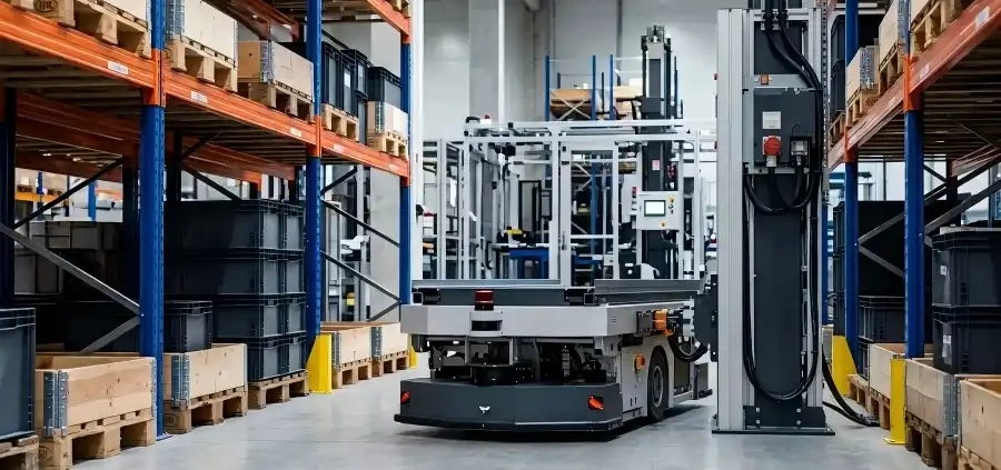
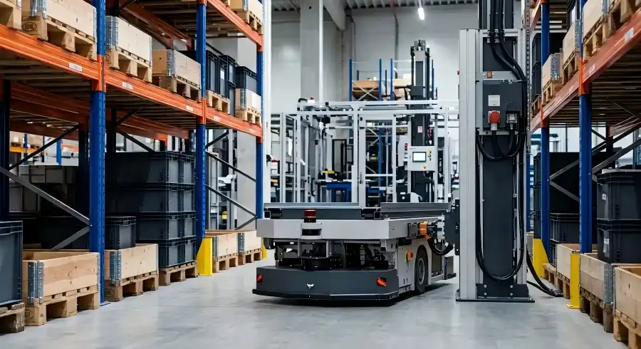
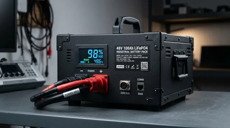
Automated guided vehicle (AGV) running in warehouse aisle for logistics automation, powered by industrial lithium battery

Commercial Disclosure: The Himax Electronics Editorial Team brings together expertise in battery products, power technologies, engineering applications, and global customer support to share practical information about battery technology, custom battery solutions, and power applications. Our content covers lithium-ion batteries, LiFePO4 batteries, battery pack design and selection, charging and power solutions, industry application guides, product updates, and official Himax Electronics news. Our goal is to help engineers, procurement professionals, and businesses better understand battery technologies and make informed decisions based on their specific application requirements. All content reflects the official editorial perspective of Himax Electronics and our commitment to providing reliable, flexible, and professional custom battery and power solutions for complex applications worldwide.

Key Takeaways

  • Choosing a lithium battery for an AGV or AMR involves more than capacity. System voltage, peak current, runtime, charging method, and available installation space all need to be considered.
  • LiFePO4 batteries offer long cycle life, good thermal stability, and a strong safety profile, making them a common choice for warehouse robots.
  • Equipment that operates frequently may benefit from opportunity charging or automated charging to minimize downtime.
  • The battery management system (BMS) should communicate properly with the vehicle control system, charging equipment, and fleet management platform.
  • Low temperatures, high temperatures, humidity, dust, and vibration may require application-specific cell selection, enclosure design, and protection.
  • When developing a custom AGV battery pack, electrical specifications, mechanical dimensions, connectors, certifications, and total lifecycle cost should all be evaluated.

Introduction

As smart warehousing, flexible manufacturing, and automated logistics continue to expand, AGVs (Automated Guided Vehicles) and AMRs (Autonomous Mobile Robots) are becoming essential equipment in factories, distribution centers, e-commerce warehouses, and automated production lines. As the vehicle’s primary power source, the battery pack affects more than just AGV and AMR runtime. It can also influence charging efficiency, fleet scheduling, operational safety, and total cost of ownership.

So, how should you choose the right AGV lithium battery or AMR lithium battery for a warehouse automation project? This guide covers the key factors to consider, including battery chemistry, capacity, voltage, charging methods, communication protocols, safety design, and operating environment.

How Do Battery Requirements Differ Between AGVs and AMRs?

AGVs typically follow magnetic strips, QR codes, reflectors, or predefined routes, so their travel paths and operating cycles tend to be relatively predictable. AMRs, on the other hand, use technologies such as LiDAR, vision sensors, SLAM navigation, and real-time algorithms to plan their routes autonomously, resulting in more dynamic operating patterns.

Although both types of equipment require a reliable power system, AMRs often carry more computing hardware, sensors, and communication modules, which may continue drawing power even when the robot is idle. As a result, an AMR battery solution must not only meet the power requirements of the drive motors but also provide stable power for navigation, sensing, control, and wireless communication systems.

Comparison AGV Battery Requirements AMR Battery Requirements
Travel Route Usually fixed, making loads easier to predict Routes change dynamically, which can cause greater variations in power consumption
Powered Equipment Drive system, controls, and basic sensors Drive system, industrial computer, LiDAR, cameras, and communication modules
Peak Power Related to startup, acceleration, and material-handling loads Related to acceleration, steering, obstacle avoidance, and computing loads
Charging Strategy Battery swapping, scheduled charging, or automated charging Automated charging or opportunity charging is commonly used
Communication Requirements CAN, RS485, etc. CAN, RS485, and more extensive battery status data exchange
Battery Design Priorities Durability, cost, and cycle life Energy density, dynamic power capability, communication, and intelligent management

Why Are LiFePO4 Batteries Well Suited for Warehouse Automation Equipment?

Traditional lead-acid batteries have a relatively low upfront cost, but they are heavy, take longer to charge, and have a more limited cycle life. Their performance can also decline significantly after repeated deep discharges. For AGVs and AMRs that operate frequently every day, frequent battery replacement can increase labor costs, spare battery inventory, and equipment downtime.

LiFePO4 batteries typically offer the following advantages:

  • Long cycle life, making them suitable for frequent charge and discharge cycles;
  • Good thermal stability, which can contribute to overall system safety;
  • High charge and discharge efficiency with relatively flexible charging strategies;
  • Lower weight than lead-acid batteries for a comparable amount of usable energy;
  • A relatively stable discharge voltage, supporting consistent equipment performance;
  • Low self-discharge, reducing routine maintenance requirements;
  • Real-time monitoring of voltage, current, temperature, and state of charge through an intelligent BMS.

However, not every AGV or AMR needs to use the same battery chemistry. For robots with limited installation space, strict weight requirements, or a need for higher energy density, other lithium-ion chemistries, such as NMC, may also be worth evaluating. The final choice should balance safety, runtime, size, weight, cycle life, and cost.

How Do You Determine the Right Voltage and Capacity for an AGV or AMR Lithium Battery?

Match the Vehicle’s System Voltage

Common AGV and AMR power systems may operate at 24V, 36V, 48V, 60V, or higher. The battery pack’s nominal voltage, fully charged voltage, and minimum discharge voltage must all be compatible with the motor controller, onboard power electronics, and charger.

Do not select a battery simply because the equipment is labeled “48V.” Different battery chemistries use different numbers of cells in series and have different full-charge and discharge cutoff voltages. Before selecting a battery, verify the controller’s allowable operating voltage range.

Estimate Capacity Based on Actual Power Consumption

A basic estimate of the required battery capacity can be calculated as follows:

Required Battery Energy (Wh) ≈ Average Equipment Power (W) × Target Runtime (h) ÷ System Efficiency

Then convert the required energy into amp-hours based on battery voltage:

Battery Capacity (Ah) ≈ Required Battery Energy (Wh) ÷ Nominal Battery Voltage (V)

For example, suppose an AMR consumes an average of 800W and needs to operate continuously for 8 hours. Assuming an overall power system efficiency of 90%, the theoretical energy requirement would be approximately:

800 × 8 ÷ 0.9 ≈ 7,111Wh

If the system uses a LiFePO4 battery pack with a nominal voltage of 51.2V, the theoretical capacity would be approximately:

7,111 ÷ 51.2 ≈ 139Ah

In an actual design, however, you also need to account for depth of discharge, aging margin, ambient temperature, peak loads, and available charging windows. For that reason, simply selecting a 140Ah battery based on the theoretical calculation may not be appropriate. A battery manufacturer will typically add a reasonable design margin based on the vehicle’s actual duty cycle.

Verify Peak and Continuous Current Requirements

Current demand can increase significantly for short periods when an AGV starts, turns, climbs a slope, lifts a load, or transports heavy materials. If the battery can handle the average load but not the peak current, the BMS may trigger overcurrent protection and cause the vehicle to shut down unexpectedly.

The following information should be provided when selecting a battery:

  • Average current during normal operation;
  • Maximum continuous current while the motors are operating;
  • Peak current during startup, climbing, or lifting;
  • Duration and frequency of peak-current events;
  • Whether the system produces regenerative current or uses regenerative braking.

How Do You Choose the Right Charging Method?

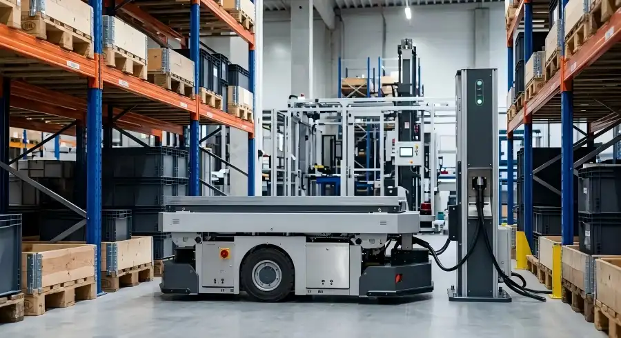
An automated guided vehicle (AGV) navigating an aisle of tall racking systems in a modern, well-lit warehouse, illustrating warehouse automation and automated material handling.

Common charging methods for AGVs and AMRs include manual plug-in charging, automatic docking, opportunity charging, and rapid battery swapping. The charging method directly affects vehicle utilization, battery capacity requirements, and warehouse scheduling strategies.

Charging Method Best Suited For Main Advantages Key Considerations
Manual Charging Small fleets with centralized overnight downtime Simple system and lower initial investment Requires manual operation and may limit continuous operation
Automatic Docking Automated warehouses and production lines High level of automation with less manual intervention Charging contacts, positioning accuracy, and communication must be compatible
Opportunity Charging Operations with frequent short idle periods and long uptime requirements Uses short breaks to replenish battery capacity Battery must support frequent charging
Rapid Battery Swapping High-load applications where downtime must be minimized Allows the vehicle to return to operation quickly after a battery change Requires spare batteries, swapping space, and standardized interfaces

If the equipment operates for only one shift per day, a larger battery pack can be used and charged during off-hours. If the equipment needs to operate around the clock, simply increasing battery capacity can add weight, consume valuable space, and increase purchasing costs. In these cases, opportunity charging or automated charging is often a better solution.

The charger and battery pack should use a compatible charging profile, with the necessary communication or hardware interlocks to verify temperature, voltage, and connection status. An unverified or incompatible charger may result in incomplete charging, repeated overvoltage protection events, or reduced battery life.

Why Is the BMS Critical to an AGV Battery Pack?

A BMS, or Battery Management System, monitors and manages the operating condition of the battery pack. In warehouse automation equipment, the BMS is more than a protection device—it also serves as the data bridge between the battery and the vehicle.

An intelligent BMS designed for AGVs and AMRs will typically include:

  • Individual cell voltage and total pack voltage monitoring;
  • Charge and discharge current monitoring;
  • Multi-point temperature monitoring;
  • Overcharge, over-discharge, overcurrent, short-circuit, and overtemperature protection;
  • Cell balancing;
  • SOC (State of Charge) estimation;
  • SOH (State of Health) estimation;
  • Charge/discharge MOSFET or contactor control;
  • Fault logging and operating data storage;
  • CAN, RS485, UART, or other communication capabilities.

SOC accuracy can directly affect vehicle scheduling. If the SOC estimate is significantly inaccurate, the fleet management system may send a vehicle to charge too early, reducing equipment utilization. It may also overestimate the remaining capacity and cause a robot to shut down in the middle of a task.

For this reason, the BMS SOC algorithm should be calibrated based on battery chemistry, load characteristics, temperature changes, and battery aging rather than relying solely on battery voltage.

What Communication Protocols and Interfaces Should You Confirm?

Even if a battery meets all voltage and capacity requirements, incompatible communication protocols can prevent it from working properly with the vehicle. Before ordering a custom AMR or AGV battery pack, confirm the following:

  • Whether the vehicle communicates with the battery through CAN, RS485, or another protocol;
  • Baud rate, node address, and message cycle;
  • Definitions for SOC, SOH, voltage, current, temperature, and other data;
  • Charge enable, discharge enable, and fault alarm logic;
  • Emergency stop, wake-up, and sleep signals;
  • Power, charging, and communication connector models;
  • Positive and negative terminal definitions and wire harness lengths;
  • Whether the charging station needs to perform a handshake with the BMS;
  • How the vehicle controller should respond if communication is interrupted.

For new projects, it is a good idea to involve the battery supplier early in vehicle development and system integration. This makes it easier to identify protocol, interface, or control-logic issues during the prototype stage instead of making extensive modifications after mass production begins.

How Does the Operating Environment Affect Battery Selection?

Low-Temperature Environments

In cold-storage facilities, warehouses in cold climates, or outdoor logistics applications, low temperatures can reduce the usable capacity and charging capability of lithium batteries. Charging at relatively high currents in very cold conditions can also accelerate battery degradation.

For low-temperature AGV applications, battery heating, thermal insulation, and temperature-control strategies may be considered. The BMS should limit or disable charging when the battery temperature is outside the acceptable charging range and resume charging once the required conditions are met.

High-Temperature Environments

High temperatures can accelerate cell aging and may also affect the reliability of electronic components and connectors. Battery enclosure design should account for heat dissipation paths, temperature sensor placement, and appropriate protection thresholds. For high-temperature production environments, it is also important to evaluate the actual internal temperature rise of the battery during continuous operation rather than relying only on ambient temperature.

Dust, Moisture, and Vibration

Food processing, chemical processing, woodworking, and some manufacturing environments may expose equipment to dust, oil, or moisture. Battery enclosures should be designed with an appropriate level of protection for the operating environment, with particular attention to connector sealing, wire harness retention, and corrosion resistance.

Vehicles that frequently travel over uneven floors, ramps, or speed bumps may also require enhanced cell retention, shock-absorbing structures, and vibration-resistant designs.

What Certifications Should You Consider for AGV and AMR Battery Packs?

Certification requirements depend on the market where the product will be sold, the shipping method, and the intended use of the complete equipment. Common testing and compliance requirements may include UN 38.3, IEC 62133, CE, UL, and documentation required for ocean or air transportation.

It is important to understand that certification of individual battery cells does not necessarily mean that the complete battery pack automatically meets the same requirements. Changes to the battery enclosure, BMS, wiring, protection devices, or pack configuration may require additional evaluation or testing.

For this reason, the battery supplier should be informed early in the project about the target market, shipping method, equipment certification plan, and customer acceptance requirements so that the appropriate testing time and costs can be factored into the project.

AGV and AMR Lithium Battery Selection Checklist

When requesting a battery solution from a manufacturer, it is helpful to provide the following project information:

  1. Equipment type and application;
  2. Power requirements of the motors, controllers, and other loads;
  3. Nominal voltage and allowable operating voltage range;
  4. Average, continuous, and peak current;
  5. Target runtime and daily operating hours;
  6. Planned charging method and available charging time;
  7. Battery installation space, weight limits, and mounting method;
  8. Operating temperature, humidity, dust, and water-resistance requirements;
  9. Communication protocol and message definitions;
  10. Connector, wire harness, and interface requirements;
  11. Target markets and certification requirements;
  12. Estimated order quantity and project timeline.

The more complete the information, the easier it is for the battery supplier to develop an accurate AGV battery solution and shorten the prototype development and vehicle validation process.

Frequently Asked Questions (FAQ)

Can AGVs and AMRs Use the Same Lithium Battery Pack?

Not necessarily. Even if two vehicles use the same nominal voltage, their power consumption, peak current, communication protocols, installation space, and charging methods may be different. The same battery should only be used when the electrical specifications, mechanical dimensions, interfaces, and control logic are fully compatible.

Is a Larger AGV Lithium Battery Always Better?

No. A battery that is too small can result in insufficient runtime and frequent charging, while an oversized battery increases cost, weight, and space requirements. The appropriate capacity should be calculated based on the duty cycle, average power consumption, charging windows, and required reserve capacity.

How Long Does an AGV LiFePO4 Battery Typically Last?

Actual battery life depends on cell quality, depth of discharge, charge and discharge rates, operating temperature, vehicle load, and maintenance practices. When evaluating whether a battery is suitable for a project, review the supplier’s cycle-life data under clearly defined test conditions rather than relying on a cycle count without supporting test parameters.

Can an AMR Automatically Recharge During Short Idle Periods?

Yes. This approach is commonly known as opportunity charging. It is well suited for equipment with demanding workloads and long uptime requirements. Before implementation, confirm the battery’s allowable charge rate, the reliability of the charging contacts, BMS-to-charger communication, and the fleet management system’s charging strategy.

Can an Older Lead-Acid AGV Be Converted to Lithium Batteries?

Some vehicles can be converted, but the process involves more than replacing the battery itself. The voltage range, charger, controller, counterweight, installation dimensions, connectors, and SOC display method should all be checked.

Lithium batteries are typically lighter than lead-acid batteries. If the vehicle was designed to use the lead-acid battery as part of its counterweight, the vehicle’s stability may need to be reevaluated after conversion.

Why Is the Battery SOC Reading Inaccurate?

Common causes include improper algorithm calibration, current-sensing errors, long periods without a full charge/discharge calibration cycle, temperature changes, and battery aging. Operating data can be used to check the current sensor, communication messages, and BMS parameters.

Do AGV Batteries Require Regular Maintenance?

Lithium batteries generally require less routine maintenance than lead-acid batteries, but connectors, wiring harnesses, mounting structures, charging contacts, abnormal temperature rise, and fault records should still be inspected periodically. During long-term storage, the battery should be kept at an appropriate SOC and stored within the temperature range recommended by the battery supplier.

What Information Is Needed for a Custom AGV Battery Pack?

At a minimum, provide the system voltage, capacity or runtime target, continuous and peak current, installation dimensions, connectors, communication protocol, charging method, operating temperature, and certification requirements. Providing vehicle power-consumption data, duty-cycle information, and specifications for the existing battery will allow the supplier to develop a more accurate solution.

About Himax Electronics

Himax Electronics specializes in lithium battery solutions for industrial equipment and intelligent logistics applications. Based on the specific requirements of AGVs, AMRs, material-handling robots, and other automated equipment, we can provide custom support for cell selection, battery pack structure, intelligent BMS design, communication protocols, connectors, and charging solutions.

Whether your project requires a 24V, 36V, 48V, or another voltage platform, or prioritizes long cycle life, fast charging, low-temperature operation, or CAN/RS485 communication, Himax Electronics can evaluate a battery solution based on your vehicle’s power requirements, available installation space, and target-market requirements.

Tol battery

As we push further into 2026, the Internet of Things is no longer about simple, low-power sensors sending tiny data packets. Today’s IoT landscape is defined by sophisticated edge computing, high-bandwidth cellular transmissions, and complex sensor arrays. These devices demand more from their power sources than ever before. For over 12 years, I’ve specialized in designing custom Li-ion packs for these exact challenges. My name is Alden, and I’m a Battery Systems Engineer here at Himax Electronics. In my experience, one of the most common failure points I see in otherwise brilliant IoT projects is an under-specified power source. That’s why I’m excited to share my insights on a solution that is quickly becoming the new standard for reliability and performance: the high-discharge 3.7V 6000mAh Li-ion battery pack.

a compact 1S2P configuration with 18650 cells

Understanding Power Demands in Modern IoT Devices

The days of a simple, steady power draw are over for most serious IoT applications. A modern industrial IoT sensor or remote gateway has a highly dynamic power profile. It might idle at a few microamps for hours, then suddenly demand several amps for a few hundred milliseconds. This “bursty” behavior is the new normal.

A common mistake I see engineers make is designing for the average current draw, not the peak. This leads to catastrophic field failures. When a device needs to power up a 4G/5G modem, actuate a motor, or fire up multiple sensors simultaneously, the battery’s voltage can plummet if it can’t handle the sudden load. This “voltage sag” or “brownout” can cause the device’s microcontroller to reset, corrupting data and leading to a spiral of failed connection attempts that drains the battery completely. A robust IoT battery must be able to handle these peaks without faltering.

Why 3.7V 6000mAh with 18A Discharge Stands Out for IoT

At Himax, we’ve focused on creating a power solution that directly addresses these modern challenges. Our 3.7V IoT battery pack is built to provide both endurance and power, serving as a reliable power solution for edge IoT devices. Let’s break down what makes this configuration so effective.

Here’s what makes our Himax IoT battery, a 1S2P 18650 battery for IoT, a game-changer:  

  •  High Capacity (6000mAh): Built with two premium 3000mAh 18650 cells in a 1S2P configuration, this pack offers a substantial 6Ah of energy. This high capacity is essential for achieving a long operational life in remote or solar-powered IoT deployments, minimizing the need for costly and frequent replacements. It’s the foundation of a low total cost of ownership.
  • Massive Discharge Capability (18A): This is the crucial spec. A continuous discharge rating of 18A means the battery can effortlessly handle the intense power spikes from LoRaWAN, NB-IoT, or 5G transmissions. This prevents voltage sag, ensuring your device remains stable and operational during its most critical tasks. This is a true high discharge IoT battery.
  • Ultra-Compact Form Factor: Space is always at a premium inside an IoT enclosure. With dimensions of just 38 × 25 × 70 mm, this rectangular pack is incredibly dense. It allows you to design smaller, more discreet devices without sacrificing power, a key advantage for asset trackers and compact industrial sensors.
  • Industrial-Grade Reliability: We designed this 3.7V 6000mAh 18650 pack for the real world. Paired with a properly designed Battery Management System (BMS), it offers excellent thermal stability and a long cycle life, operating reliably in harsh environments typically ranging from -20°C to 60°C.


Real-World IoT Applications Where This Pack Excels

The combination of high capacity and high discharge in this Li-ion battery for IoT devices makes it incredibly versatile. Here are a few applications where I’ve seen this type of pack deliver exceptional results:

Smart Agriculture Sensors: A soil moisture and nutrient sensor array might take readings every hour, but once a day it needs to transmit a large data log over a cellular network. That transmission burst requires a high discharge IoT battery to ensure the data gets through, while the 6000mAh capacity allows it to last for an entire growing season. This is a perfect use case for a high capacity battery for remote monitoring.

Industrial Asset Tracking & Cold Chain: A tracker on a shipping container needs to survive for months while providing periodic GPS/cellular location updates. When moving through areas with poor signal, the modem boosts its power, drawing significant current. An 18A continuous discharge battery ensures the tracker doesn’t fail when it’s needed most.

Remote Environmental Monitoring: Consider a solar-powered gateway in a remote forest monitoring for fire risk. The system charges during the day and runs on its 3.7V 6Ah battery for IoT at night, powering sensors and a satellite modem. The battery’s ability to handle high peak currents is critical for reliable data transmission, no matter the conditions.

designed for high-discharge industrial IoT applications.

Engineering Tips: Integrating High-Discharge Packs Without Over-Engineering

From my experience as Alden, a Battery Systems Engineer, I believe a great battery is only half the solution. Proper integration is key. Here’s what to look for when incorporating a high-performance 3.7V IoT battery pack into your design:

  • Don’t Skimp on the BMS: The Battery Management System is the brain of your power system. For a high-discharge pack, ensure your BMS provides accurate cell balancing, over-current protection that aligns with the 18A peak, and under-voltage/over-voltage cutoffs to maximize cycle life.
  • Consider Your Connectors: A common point of failure is a connector that isn’t rated for the peak current. An 18A pulse will generate heat and voltage drop across a flimsy connector. Use connectors with an appropriate current rating to ensure all that power makes it to your device.
  • Thermal Management is Your Friend: While our 18650 cells are incredibly stable, all batteries generate heat under load. In a tight, sealed enclosure, ensure there’s a thermal pathway for this heat to dissipate. Even a small piece of thermally conductive material can make a huge difference in long-term reliability.
  • Himax 3.7V 6000mAh Li-ion IoT battery pack

Looking Ahead — The Role of Reliable Batteries in Scaling IoT Deployments

Looking ahead, as Alden at Himax Electronics, I see the reliability of each node becoming exponentially more important. The difference between a pilot project and a global deployment of a million devices often comes down to Total Cost of Ownership (TCO). A robust, reliable, and correctly specified IoT battery is the single most effective way to reduce TCO. It means fewer truck rolls for replacements, less downtime, and a more trustworthy brand reputation. Choosing a powerful and durable power source like a custom 3.7V battery pack for IoT OEM is not an expense; it’s an investment in the scalability and success of your entire platform.

At Himax Electronics, we’ve built our reputation on being a trusted partner for dozens of IoT brands. See our full IoT battery portfolio. If you’re building IoT sensors, gateways, or industrial edge devices and need a dependable 3.7V high-discharge battery partner, reach out to Himax Electronics today. Let’s discuss your project requirements and custom options.


Author: Alden, Battery Engineer – Manufacturing & Quality Control
Published: March 24th, 2026


More information about Li-ion batteries:

Why Lithium-Ion Batteries Must Be Charged Using the CC/CV Method

Why Maximum Continuous Discharge Current is Critical for Your Battery Selection


603450 LiPo battery dimensions 6.0 x 34.0 x 53.0 mm with built-in PCM protection board

Introduction

LiPo 603450 battery selection is one of the most important decisions I make when customers ask me to recommend a reliable power source for a GPS tracker. I’m Caleb, a Battery Engineer at Himax Electronics, and I specialize in BMS & Protection Systems for lithium battery packs used in compact, high-reliability devices. In my daily work, I help customers build safer and more stable battery solutions with PCM/BMS protection against overcharge, over-discharge, over-temperature, and short circuit.

603450 LiPo for GPS tracker applications stands out because GPS devices often operate in demanding real-world conditions: long standby cycles, frequent location uploads, outdoor temperature variation, vibration, and very limited internal space. From my engineering perspective, the battery must be compact, dependable, and easy to integrate without sacrificing safety. That is exactly why I often recommend the 3.7V 1000mAh LiPo battery in the 603450 format. It offers a practical balance of size, runtime, protection, and discharge capability for many modern tracker designs.

LiPo 603450 3.7V 1000mAh battery with PCM for GPS tracker, compact 6x34x53mm size

Technical Specifications

LiPo 603450 battery specifications matter because GPS tracker designers usually need clear electrical and mechanical data before finalizing their product layout.

Parameter Specification
Model LiPo 603450 (1s1p)
Nominal Voltage 3.7V
Max Charging Voltage 4.2V
Nominal Capacity 1000mAh
Cell Dimensions 6.0 × 34.0 × 53.0 mm
Typical Dimension Reference 603450 53mm battery
Continuous Discharge Current 1A
Battery Type Rechargeable Lithium Polymer
Protection PCM protection: overcharge, over-discharge, short circuit, over-temperature
Recommended Charge Current 0.2C to 0.5C
Standard Charge Current 200mA (0.2C)
Max. Charge Current 500mA (0.5C)
Max. Continues Discharge current 1000mA (1C)
Approximate Weight 17g
Cycle Life 300–500 cycles typical at standard conditions
Operating Temperature (Discharge) -10°C to 60°C
Operating Temperature (Charge) 10°C to 45°C
Lead Configuration Customizable wire length and connector
Integration Option NTC / custom PCM / connector / label available

Why This Battery is Ideal for GPS Trackers

603450 LiPo for GPS tracker designs works so well because it matches the real electrical behavior of most portable tracking devices. In many GPS trackers, the average current is relatively low during standby, but there are short bursts of higher current during GSM, LTE, or GNSS transmission. A 1A continuous discharge LiPo is usually more than enough for this type of device, especially when the hardware and firmware are optimized for low-power operation.

LiPo 603450 battery is also a very practical mechanical choice. With dimensions of 6x34x53mm, this cell fits into compact tracker housings where every millimeter matters. I often see customers comparing several sizes, but many of them eventually return to this format because it offers better runtime than smaller cells without becoming too bulky for portable use.

GPS tracker battery reliability is especially critical for devices used in fleet management, asset tracking, pet tracking, personal safety, and medical-related portable electronics. In these applications, an unexpected shutdown can mean lost data, missed location updates, or even safety risks. That is why I strongly prefer a LiPo battery with PCM for field devices. The protection circuit helps reduce the chance of battery abuse during charging, storage, shipping, and real-world use.

Compact LiPo battery 6x34x53mm designs like this one also help product teams simplify enclosure planning. For many GPS products, designers need a battery that is thin enough for a modern industrial design but still large enough to support practical working time. The 603450 format is often the sweet spot.

603450 LiPo battery dimensions 6.0 x 34.0 x 53.0 mm with built-in PCM protection board

Key Advantages & Real-World Performance

LiPo 603450 battery performance is not just about the datasheet; it is about how the battery behaves inside a real product. Based on my experience supporting customer projects, these are the biggest advantages:

  • Balanced size and capacity
    The 3.7V 1000mAh LiPo batterygives GPS devices a strong balance between compact dimensions and useful runtime.
  • Stable discharge for tracker electronics
    A 1A continuous discharge LiPois suitable for low-power communication modules, MCU control boards, and scheduled transmission cycles.
  • Added field safety with PCM
    A LiPo battery with PCMhelps protect the cell from overcharge, over-discharge, short circuit, and temperature-related risks.
  • Flexible customization
    I can adapt wire length, connector type, NTC, and PCM settings depending on the customer’s tracker PCB and housing.


603450 LiPo for GPS tracker projects has repeatedly proven to be a reliable choice in my work. I have supported customers who needed battery solutions for compact GPS tracking units where space was limited and uptime was critical. In those cases, the 603450 format performed well because it delivered enough capacity for practical operation while staying thin and integration-friendly. From an engineer’s point of view, that combination is hard to beat.

Comparison with Other Common GPS Batteries

GPS tracker battery comparisons are important because designers often evaluate multiple pouch cell sizes before locking the final BOM.

Battery Model Typical Capacity Size Main Advantage Main Limitation
502030 ~250–350mAh Smaller Very compact Much shorter runtime
603048 ~800–900mAh Slightly shorter Good for tighter layouts Less capacity than 603450
603450 1000mAh 6 × 34 × 53 mm Best balance of size and runtime Slightly larger than ultra-compact cells

LiPo 603450 battery usually wins when runtime is more important than saving a few extra millimeters. Compared with a 502030 cell, the 603450 gives significantly more capacity, which means fewer charging intervals and a better user experience. Compared with 603048, it offers a little more room for energy storage while remaining compact enough for many handheld or concealed tracker designs.

Best battery for GPS tracker 2025 will depend on the device’s power profile, but for many mainstream trackers, I see the 603450 as one of the most practical options because it avoids the tradeoff of being too small to last or too large to fit.

Installation & Integration Tips for GPS Device Designers

603450 LiPo for GPS tracker integration should always start with actual current measurements, not assumptions. I recommend that designers measure average standby current, pulse current during transmission, and charging behavior under real firmware conditions.

LiPo 603450 battery integration becomes easier when you plan for these details early:

  1. Leave space for PCM and wire routing
    The cell size is only part of the battery footprint. The PCM board, leads, insulation, and connector also require layout space.


  1. Validate charge voltage and current
    A 7V 1000mAh LiPo batteryshould be charged with a proper CC/CV lithium charging profile ending at 4.2V.


  1. Add thermal consideration
    If your GPS device is used in vehicles or outdoor enclosures, I strongly recommend temperature monitoring and careful charging control.


  1. Prevent compression and puncture risk
    LiPo pouch cells should never be mechanically squeezed by the housing or screws.


  1. Match the connector to your assembly flow
    I often help customers choose between JST-style connectors, solder tabs, or custom harnesses depending on production needs.


LiPo battery with PCM systems are much more effective when the whole device is designed around battery safety, not when PCM is treated as the only line of defense. If your product needs a custom pack, protection threshold adjustment, or connector support, this is where an engineering partner really matters.

For related battery solutions, I also recommend linking to your broader lithium polymer battery pages, custom battery pack pages, and team expertise pages such as the breast pump battery project page that reflects our engineering capabilities and application experience.

GPS tracker powered by Himax 603450 1A continuous discharge LiPo battery

Safety First: How Our PCM Makes the Difference

LiPo 603450 PCM protection is where I spend a lot of my engineering time, because protection design is what turns a good cell into a dependable battery solution. At Himax Electronics, I focus on building battery packs that do more than just provide voltage and capacity. My goal is to make them safer and more stable in real use.

LiPo battery with PCM helps defend against the most common failure risks in compact electronics:

  • Overcharge protectionhelps prevent the cell voltage from rising beyond safe limits.
  • Over-discharge protectionhelps avoid deep discharge that can permanently damage the battery.
  • Short circuit protectionreacts quickly to wiring faults or accidental conductive contact.
  • Over-temperature protectionadds another layer of control for applications exposed to harsh environments.

603450 LiPo for GPS tracker applications particularly benefit from PCM because many trackers are used remotely, inside vehicles, outdoors, or in devices that users may not charge correctly. In my experience, robust protection is not optional. It is one of the reasons a battery solution survives real-world use.

If your design needs a smarter protection strategy, this is also where a custom BMS or enhanced PCM can make a meaningful difference, especially for regulated or mission-critical applications.

FAQ

LiPo 603450 battery questions often come from device designers and purchasing teams, so here are the answers I give most often.

1. Is the 603450 a good GPS tracker battery?

603450 LiPo for GPS tracker use is an excellent choice for many compact devices because it balances thin size, 1000mAh capacity, and practical discharge capability.

2. What does PCM mean in a LiPo battery?

LiPo battery with PCM includes a protection circuit module that helps prevent overcharge, over-discharge, short circuit, and sometimes over-temperature.

3. Is 1A continuous discharge enough for a GPS tracker?

1A continuous discharge LiPo is enough for many GPS tracker designs, especially low-power devices with periodic transmission. Final validation should always be based on real current testing.

4. What are the exact dimensions of this battery?

Compact LiPo battery 6x34x53mm refers to a typical size of 6.0 × 34.0 × 53.0 mm, which is why some buyers also search for a 603450 53mm battery.

5. How long can a 1000mAh battery power a GPS tracker?

3.7V 1000mAh LiPo battery runtime depends on standby current, transmission interval, network type, and temperature. A low-power design can achieve useful operating time, but exact hours must be tested in the final device.

6. Can Himax Electronics customize this battery?

LiPo 603450 battery solutions can be customized with different connectors, wire lengths, labels, NTC, and PCM settings based on your device requirements.

7. Is this the best battery for GPS tracker 2026 designs?

Best battery for GPS tracker 2026 depends on your housing size and power budget, but the 603450 is one of the strongest options for compact trackers needing a reliable 1000mAh class cell.

Conclusion

LiPo 603450 battery remains one of my preferred recommendations for GPS tracker projects because it combines compact dimensions, practical 1000mAh capacity, stable 1A discharge, and essential PCM safety protection. As an engineer, I always look for the best balance between electrical performance, mechanical fit, and long-term reliability, and this battery checks those boxes for many real-world tracking applications.

603450 LiPo for GPS tracker projects can be further optimized with custom wires, connectors, PCM settings, and integration support. If you are designing a new tracker or improving an existing one, I’d be glad to help you evaluate the right battery configuration for your product. You can also explore our lithium battery product pages, learn more about our engineering capabilities, or reach out through our contact page for a custom solution.

Leave a comment or contact us for custom battery solutions.

Author: Caleb, Battery Engineer – BMS & Protection Systems, Himax Electronics
Published: March 16th, 2026


More information about LiPo batteries:

How to Maximize Performance and Safety with LiPo Batteries

Swollen LiPo Battery: Causes, Risks, and Safe Solutions

High-Discharge LiPo Drone Battery 22.2V 5000mAh 35C