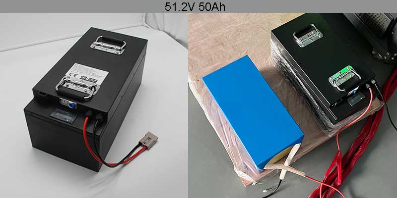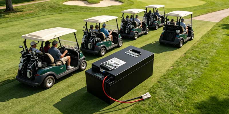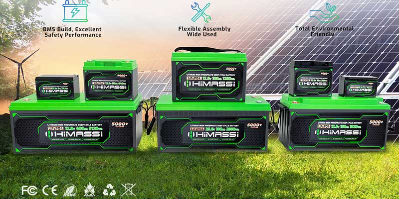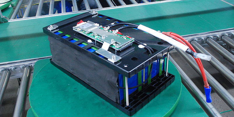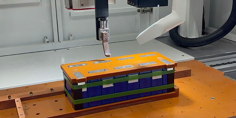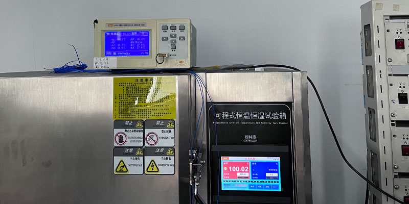
51.2V 50Ah LiFePO4 golf cart battery pack with SC50 discharge connector and Pinzi Head charge port from Himax Electronics
Caleb  ·  Battery Engineer — BMS & Protection Systems

Focused on battery management systems and protection design, Caleb develops PCM/BMS solutions with overcharge, over-discharge, thermal, and short-circuit protection to enhance safety and operational stability across applications.


Lead acid has powered golf carts for decades — and for a long time, the case against switching was simple: lithium costs more up front. That calculation has shifted. With LiFePO4 cycle life now exceeding 2,000 full charges, golf course operators and fleet buyers are asking a different question: not whether to switch, but when and what to specify. This guide answers both, using the Himax 51.2V 50Ah LiFePO4 pack as the working reference.


KEY TAKEAWAYS

› LiFePO4 chemistry is the correct choice for golf carts: thermally stable, non-toxic, and inherently safer than NMC or lead acid under abuse conditions.

› 51.2V nominal (16S LiFePO4) is a direct drop-in replacement for 48V lead-acid systems — no motor controller changes required in most carts.

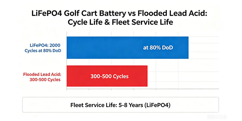
› 2,000-cycle rated life at 80% depth of discharge translates to 5–8 years of daily fleet use, versus 300–500 cycles for flooded lead acid.

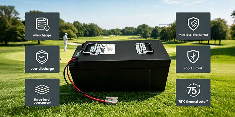
› The BMS in this pack provides six protection layers: overcharge, over-discharge, overcurrent (three thresholds), short circuit, and thermal cutoff at 75°C NTC.

› 2,560Wh of usable energy delivers 35–50km of real-world range per charge for a standard golf cart — depending on terrain, load, and ambient temperature.

› Maintenance cost savings from eliminating water top-ups, equalization charges, and early replacement typically offset the higher purchase price within 2–3 years.

Electric golf cart powered by LiFePO4 battery upgrade driving on sunny golf course with 35-50km range per charge

Why Is LiFePO4 the Right Chemistry for Golf Carts?

LiFePO4 (lithium iron phosphate) is the safest lithium chemistry for vehicle applications. Its thermal stability means it does not enter runaway when overcharged or punctured — a critical advantage for carts used in close proximity to people on golf courses, resorts, and campuses.

Thermal stability compared with other lithium chemistries

NMC and NCA lithium cells release oxygen when thermally stressed, which feeds combustion. LiFePO4 cells do not — the phosphate-oxygen bond is significantly stronger and does not break down at temperatures a golf cart battery might realistically encounter. The Himax pack’s BMS adds a 75°C NTC thermal cutoff as a second protection layer, but the underlying cell chemistry is the primary safety feature.

Why 51.2V (16S) works with 48V golf cart systems

A 16S LiFePO4 pack has a nominal voltage of 51.2V (3.2V × 16 cells) and a full-charge voltage of 57.6V (3.6V × 16). Most 48V golf cart motor controllers are rated to operate across 40–60V — which means this pack is electrically compatible without controller replacement. The nominal voltage is close enough to 48V that torque and speed characteristics remain familiar to drivers, while the higher peak voltage delivers noticeably better hill-climbing performance.

What the 2,000-cycle rating means in a fleet context

The Himax 51.2V 50Ah pack is rated for 2,000 cycles to 70% remaining capacity at standard depth of discharge. In a golf course context where a cart is discharged and recharged once per day, this translates to roughly 5.5 years before the pack drops below 70% of original capacity. Most fleet operators find the pack remains serviceable for 7–8 years. Flooded lead acid at a similar depth of discharge rarely exceeds 300–500 cycles — one-sixth the life.


What Are the Full Specifications of the Himax 51.2V 50Ah Pack?

Model 512-50BP is a 16S1P LiFePO4 pack using LF28148115 cells, delivering 51.2V nominal, 50Ah minimum capacity, 2,560Wh of energy, and a 40A maximum continuous discharge current. The BMS provides six-layer protection with cell-level balancing at 3.5V ± 0.025V.


Model

512-50BP

Himax reference

Nominal voltage

51.2V

16S LiFePO4 configuration

Capacity (min)

50Ah

0.2C discharge to 40V

Energy

2,560Wh

Usable per charge

Charge voltage

57.6V

CC/CV method

Std. charge current

5A

12-hour standard charge

Max charge current

10A

Fast charge option

Std. discharge current

10A

Normal operating load

Max continuous discharge

40A

2,048W at nominal V

Cycle life

2,000 cycles

≥70% capacity retained

Discharge cut-off

40V

BMS hard cutoff

Internal impedance

≤ 35mΩ

Pack level

Dimensions

400×220×180mm (±3mm)

L × W × H

Output wire

AWG10, 304.8mm

3135 specification

Charge connector

Pinzi Head

Dedicated charge port

Discharge connector

SC50

High-current rated

Charge temp range

0°C to 45°C

Do not charge below 0°C

Discharge temp range

-20°C to 60°C

Wide operating window

Storage temperature

-10°C to 45°C

Long-term storage

Warranty

2 years

From shipment date

Six-layer BMS protection for 51.2V LiFePO4 golf cart battery including overcharge over-discharge three-level overcurrent short circuit and 75°C thermal cutoff

BMS protection parameters — what Caleb’s team specifies

The protection circuit is built around the SH367005BAB IC (×4) with LGSE10R046B and LR046N10SM2 MOSFETs (×12). The table below covers every protection threshold as shipped:


Protection function Threshold / setting Delay / reset
Overcharge detect 3.75V ± 0.025V per cell Delay: 0.5–1.5s  |  Reset: 3.55V
Over-discharge detect 2.2V ± 0.08V per cell Delay: 0.5–1.5s  |  Reset: 2.7V
Overcurrent (charge) 80A ± 16A Delay: 0.5–1.5s
Overcurrent (discharge) level 1 160A ± 32A Delay: 0.5–1.5s
Overcurrent (discharge) level 2 320A ± 64A Delay: 50–150ms (fast trip)
Short circuit External short detection Reset: release load
Cell balancing Balances at 3.5V ± 0.025V Balance current: 36 ± 10mA
Thermal cutoff (NTC) 75°C surface trigger Automatic protection


How Far Will a Golf Cart Lithium Battery Take a Golf Cart on a Single Charge?

With 2,560Wh of usable energy, a standard 4-seat golf cart drawing 30-50A on average will cover 35-55km per charge on flat terrain. However, hilly courses, full passenger loads, and cold weather reduce that figure. Therefore, correct depth-of-discharge management significantly extends pack life.

Flat Golf Course – Standard 4-Seat Cart

For example, a typical 4-seat cart on flat terrain draws approximately 15-25A at cruise speed. At 20A average draw and 51.2V nominal, power consumption is roughly 1,024W. As a result, the 2,560Wh pack delivers about 2.5 hours of continuous drive time — equivalent to 48-56km at 20-22km/h cart speed. Moreover, most 18-hole courses require only 12-16km per round. Consequently, one charge comfortably covers 3-4 full rounds.
Average draw: 15-25A | Range (flat): 48-56km | Rounds per charge: 3-4 (18-hole)

Hilly Resort or Country Club Course

In contrast, steep elevation changes increase motor draw significantly. For instance, peak climbing current can reach 35-40A on a 15% grade. Thus, the average draw over a hilly course rises to 30-38A, cutting range to 30-40km. Nevertheless, the 40A maximum continuous discharge rating of this pack handles sustained climbing loads without triggering BMS overcurrent protection.
Average draw: 30-38A | Range (hilly): 30-40km | Peak climb current: ≤40A (within spec)

Resort Shuttle and Campus Transport – Higher Loads

Similarly, 6-seat utility carts carrying luggage or equipment draw 30-45A continuously. At 40A / 51.2V, peak power is approximately 2,048W. As a result, range at this load is 25-35km — still sufficient for a full resort property loop with buffer. Additionally, the SC50 discharge connector is rated for sustained high-current draw without contact heating at these levels.
Continuous draw: 30-45A | Range: 25-35km | Peak power: 2,048W at 40A

Cold-Weather Operation

Finally, the pack’s discharge temperature range runs to -20°C, but cold significantly affects usable capacity. For example, the specification data shows ≥60% capacity retention at -10°C after standard charge at 20°C. Therefore, operators in cold climates should expect 65-75% of warm-weather range on very cold days. Importantly, they should not charge below 0°C — the BMS will prevent charging in that range to protect cell integrity.

LiFePO4 vs. Lead Acid vs. Other Lithium: Which Battery Wins for Golf Carts?

LiFePO4 wins on cycle life, weight, maintenance, and total cost of ownership for any fleet operated more than 250 days per year. Lead acid retains an advantage only on purchase price and charger compatibility in legacy fleets with no budget for infrastructure updates.


Type Cycle life Weight (equiv.) Maintenance Safety TCO (5 yr)
LiFePO4 51.2V  ★ 2,000+ cycles ~55% lighter None Excellent Lowest
Flooded lead acid 300–500 cycles Baseline Weekly water top-up, equalization Fair Highest
AGM lead acid 400–600 cycles Slightly lighter Occasional equalization Good High
NMC lithium 500–1,000 cycles ~60% lighter None Moderate Medium
NiMH (older tech) 500–800 cycles ~30% lighter Low Good Medium-high

Cycle life comparison chart LiFePO4 golf cart battery 2000 cycles at 80% DoD versus flooded lead acid 300-500 cycles showing 5-8 years fleet service life


What Are the Most Expensive Mistakes Golf Cart Battery Buyers Make?

The costliest mistakes in golf cart battery procurement are not choosing the wrong chemistry. Instead, they are specifying the wrong voltage tier, ignoring charge temperature limits, or assuming all LiFePO4 packs have equivalent BMS protection. Therefore, each of these errors shortens pack life or creates safety exposure.

Mistake 1: Charging Below 0°C

First, LiFePO4 cells form lithium plating on the anode when charged in sub-zero temperatures. For this reason, the Himax BMS blocks charging below 0°C. However, if an operator overrides this protection — or uses a non-LiFePO4 charger — permanent capacity loss results. Consequently, this is the single most common cause of premature pack failure in cold-climate fleet deployments.

Mistake 2: Using a 48V Lead Acid Charger on a 51.2V LiFePO4 Pack

Similarly, a 48V lead acid charger terminates at approximately 58.4V. Nevertheless, this is close to, but not the same as, the 57.6V CC/CV profile required for this pack. As a result, voltage differences of this magnitude accelerate cell aging and can trigger overcharge protection on individual cells before the pack is full. Thus, always use a charger designed for 16S LiFePO4 chemistry.

Mistake 3: Discharging Consistently to Cut-Off Voltage

In addition, running any lithium pack to its BMS cut-off voltage for every cycle is the fastest way to shorten life. Specifically, the 2,000-cycle rating applies at 80% depth of discharge. However, discharging to 100% DoD consistently reduces cycle life to approximately 800–1,000 cycles. Therefore, fleet operators should configure their charging schedule so carts are plugged in after each round — not after two or three.

Mistake 4: Ignoring the BMS Protection Tier When Sourcing Cheaper Alternatives

Moreover, not all LiFePO4 packs include three-tier overcurrent protection and thermal cutoff. For example, a pack with only basic overcharge and over-discharge protection is a lower-cost product. Nonetheless, it carries meaningfully higher risk in a fleet environment. Hence, verify the full BMS specification — IC model, MOSFET count, and NTC thermal trigger — before purchasing based on price.

Mistake 5: Neglecting Storage SoC During Off-Season

Finally, golf courses in seasonal climates may store carts for 3–6 months. In fact, LiFePO4 cells stored at full charge for extended periods degrade faster than cells stored at 30–50% SoC. For this reason, the Himax pack ships at 30–70% SoC. Accordingly, charge to 50% before long-term storage and recharge every 3 months to prevent deep self-discharge.

Frequently Asked Questions

The questions below are the ones procurement managers and golf course fleet operators most commonly ask when evaluating a 51.2V LiFePO4 upgrade. Each answer is written to stand alone as a complete, citable response.

Is 51.2V LiFePO4 compatible with my existing 48V golf cart?

In most cases, yes. A 16S LiFePO4 pack operates between 40V (discharge cutoff) and 57.6V (full charge), which falls within the operating range of the majority of 48V golf cart motor controllers. Verify your controller’s voltage tolerance in its documentation — look for a stated range of 40–58V or similar. If your cart has a hard 48V nominal controller, consult the manufacturer before installing a 51.2V pack.

How long does a full charge take?

At the standard 5A charge current using a 57.6V/5A charger, a full charge from empty takes approximately 10–12 hours — suitable for overnight charging. At the maximum 10A charge current with a compatible fast charger, charge time drops to approximately 5–6 hours. Do not use chargers above 10A; the BMS will trigger overcurrent protection and the charge will not complete.

How many rounds of golf can this battery power per charge?

On a flat 18-hole course, each round requires approximately 12–16km of cart travel. At the conservative range estimate of 35km per charge (hilly terrain, full load), this pack covers 2–3 full rounds. On flat terrain with light loads, 4–5 rounds per charge is achievable. For busy tournament days with continuous cart use, a two-pack rotation with overnight charging on both is the recommended fleet configuration.

What certifications does this pack carry?

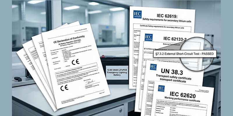
The Himax 51.2V 50Ah pack is compiled under GB/T18287-2013, UL1642, and CE61960 technology standards. Mechanical performance testing includes crush, drop (1 meter onto concrete), and vibration (XYZ axes) with no fire, explosion, or leakage. Cell safety testing covers overcharge, over-discharge, short circuit, and heating scenarios. Certification documentation is available on request for procurement records.

What maintenance does a LiFePO4 golf cart battery actually require?

Essentially none, compared with flooded lead acid. There is no water to top up, no equalization charging required, and no terminal corrosion to clean. The only maintenance task is monitoring the BMS indicator (if fitted) for fault codes, and ensuring the pack is stored at 50% SoC during off-seasons longer than 3 months. Quarterly recharging during storage is recommended to prevent deep self-discharge.

What is the warranty and what does it cover?

The pack carries a two-year warranty from the date of shipment. Himax guarantees replacement for defects proven to result from the manufacturing process. Damage from customer abuse, incorrect chargers, charging below 0°C, or mechanical impact is not covered. For OEM fleet purchases, extended warranty terms can be negotiated — contact Himax directly.


Why Do Golf Cart Fleet Operators Source from Himax Electronics?

Himax designs and manufactures LiFePO4 battery packs end-to-end — from cell sourcing through BMS development to final assembly and QC. For golf course fleets and OEM buyers, this means a single accountable supplier for cells, protection electronics, and pack-level performance guarantees.
  • BMS designed in-house, not sourced as a commodity. Caleb’s team develops PCM/BMS solutions with application-specific protection thresholds — including the three-tier overcurrent protection and NTC thermal trigger in this pack. The IC and MOSFET selection is verified against real golf cart load profiles, not generic datasheets.
  • LiFePO4 cell quality verified at batch level. The LF28148115 cells in this pack are tested for capacity, impedance, and safety performance at intake. Cell authenticity and batch records are available for OEM procurement audit.
  • Configurable pack dimensions and connectors. The standard 400×220×180mm form factor fits most golf cart battery compartments. Connector type, wire length, and output configuration can be adjusted for OEM builds with a revised drawing.
  • Fleet-scale production with stable supply. Golf course procurement often involves 20–100+ units per order. Himax maintains production capacity for volume OEM orders with consistent cell sourcing and BMS batch testing.
  • Two-year warranty with documented QC backing. Every pack undergoes pre-shipment voltage, impedance, and BMS function checks. Warranty claims are supported by production batch records — not just a warranty card.


Ready to upgrade your golf cart fleet to LiFePO4?

Tell us your cart model, fleet size, and charging infrastructure. We’ll respond with a compatible configuration and volume pricing within one business day.

www.himaxelectronics.com  |  Request a Fleet Quote


Battery for home alarm system installed in outdoor perimeter infrared sensor

By Joan | Battery Engineer – Custom Pack Development · Himax Electronics

Specializing in custom battery pack development. Joan works closely with OEM clients to optimize voltage, capacity, and form factor. His work supports scalable mass production with strict quality control and long-term reliability.

Choosing the right battery for home alarm system is the first decision that determines long-term reliability. I have spent years on the factory floor and in client meetings. Yet one pattern never changes. Typically, security hardware engineers obsess over sensor accuracy, transmission range, and tamper detection. However, the battery gets selected last — almost as an afterthought.

Consequently, three months after deployment, the field service calls start. Sensors drop offline. Control panels beep every 30 seconds. Technicians drive out to swap batteries across dozens of locations. The product works perfectly. In contrast, the power solution does not.

If you are a security system manufacturer, OEM integrator, or large-scale procurement buyer, this guide is for you. We will break down exactly how alarm system power architecture works. We will show where standard batteries fail at scale. And we will explain what a properly engineered custom battery solution looks like in practice.

Understanding the Power Architecture of a Home Alarm System

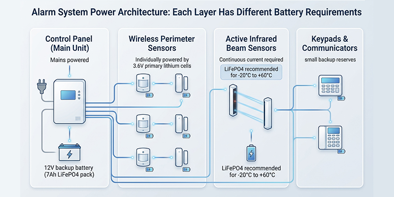
Before selecting any battery for home alarm system, you need to understand what you are actually powering. A modern home or commercial alarm system is not a single device. It is a distributed network of subsystems. Each subsystem has different power requirements.

The Control Panel (Main Unit)

The control panel is the brain of the system. It is typically mains-powered (AC). However, it requires a sealed backup battery — almost universally a 12V lead-acid or LiFePO4 pack — to maintain operation during a power outage. This is the battery most people think of when they hear “battery for home alarm system”. The most common specification is 12V 7Ah. Larger installations may call for 12V 12Ah or 17Ah packs. This battery must sustain the panel, sirens, and communication modules for a defined standby period — typically 24 to 72 hours per NFPA 72 and EN 50131 standards.

Wireless Perimeter Sensors (PIR, Door/Window, Infrared Beam)

These are the workhorses of perimeter security. Passive infrared (PIR) detectors, magnetic door/window contacts, and active infrared intrusion sensors are most often battery-powered. They use either primary lithium cells (3.6V LS14500, CR123A) or rechargeable packs. Their power consumption is ultra-low in standby mode (often under 1 µA). It spikes only during detection events and wireless transmission. Battery life for these sensors typically ranges from one to five years. The actual life depends on chemistry, trigger frequency, and ambient temperature.

Active Infrared (AIR) Beam Sensors for Perimeter Security

Active infrared intrusion sensors operate differently from passive PIR devices. The transmitter emits a continuous or pulsed infrared beam. The receiver monitors it constantly. This continuous operation demands more current — typically 1–10 mA in active mode. Therefore, battery selection becomes especially critical. Outdoor perimeter beam detectors operating at -20°C in a Nordic winter or +50°C in a Gulf Coast installation require a power source engineered for that environment. A standard AA cell will not work reliably.

Backup Power for Alarm Communicators and Keypads

Wireless communicators and remote keypads often carry their own small backup reserves. These are frequently overlooked in system-level power budgeting. However, a communicator that goes dark during a grid outage defeats the purpose of the entire installation.

Understanding this layered architecture is the starting point for any serious procurement decision. The battery for home alarm system in each layer has different chemistry, voltage, capacity, and environmental requirements.

12V alarm system battery backup power architecture diagram for control panel and sensors

Why Standard Batteries Fail at Scale: The Real Cost of Generic Power

In residential single-unit deployments, a standard 12V 7Ah SLA battery from a general distributor works well enough. You install it, forget it for three years, then replace it. That is fine.

But scale that to 500 sensor nodes across an industrial perimeter, or a portfolio of 2,000 alarm panels in a managed security service. The economics change completely.

The Beeping Problem

Walk into any forum where security installers and system integrators gather. The most discussed frustration is the same: alarm panels and wireless sensors start chirping every 30 seconds because of low battery warnings. This is not a nuisance — it is a service call. For large deployments, staggered battery degradation means you are perpetually dispatching technicians. When individual sensors in a large network reach end-of-life at random intervals, the maintenance overhead becomes a major hidden cost. That cost was not in the original project budget.

Temperature-Driven Capacity Loss

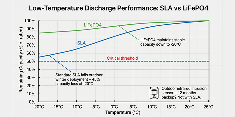
Standard sealed lead-acid batteries lose a significant portion of their rated capacity in cold environments. At 0°C, a typical SLA battery delivers roughly 80% of its rated capacity. At -20°C — entirely normal for outdoor perimeter security in northern climates — that figure drops to approximately 50–60%. For example, an outdoor infrared intrusion sensor specified for 12 months of backup operation with a standard battery might fail in six months during a cold winter. That is a security gap, not just a maintenance issue.

Lithium iron phosphate (LiFePO4) chemistry maintains stable capacity down to -20°C. Therefore, it is the correct choice for any outdoor battery for home alarm system and commercial perimeter applications.

Batch Inconsistency in Generic Batteries

When you purchase commodity batteries at scale, you are buying from a distribution chain that sources from multiple cell batches. These batches often come from different factories. Capacity variance of 10–15% across a batch is not unusual. For sensors that rely on precise low-battery detection thresholds communicated via the panel’s BMS, this variance translates into unpredictable warning timelines. Some sensors alarm early. Others fail silently before triggering a warning at all.

BMS Incompatibility and False Low-Battery Signals

This is a pain point I see repeatedly with OEM clients. Many modern wireless intrusion sensors and control panels communicate battery health data back to the central management platform. A non-OEM battery without a properly tuned Battery Management System (BMS) may report incorrect state-of-charge data. It may trigger false low-battery alerts. Or it may fail to communicate at all. The result is unnecessary service calls and eroded trust in the system’s reliability.

Battery Chemistry Comparison: Choosing the Right Technology

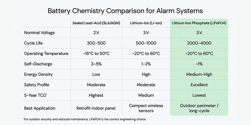
Not all battery chemistries are equal for alarm applications. Here’s how the three main technologies compare across the criteria that matter most for security deployments.

Parameter Sealed Lead-Acid (SLA/AGM) Lithium-Ion (Li-ion) Lithium Iron Phosphate (LiFePO4)
Nominal Voltage 12V (6-cell) 3.6–3.7V/cell 3.2V/cell
Cycle Life 300–500 cycles 500–1,000 cycles 2,000–4,000 cycles
Operating Temperature -15°C to 50°C -20°C to 60°C -20°C to 60°C
Self-Discharge (per month) 3–5% 1–2% ~1%
Energy Density Low High Medium-High
Safety Profile Moderate (sulfuric acid) Moderate (thermal runaway risk) Excellent (stable chemistry)
Maintenance Low (VRLA) None None
Cost (initial) Lowest Medium Medium-High
5-Year TCO Highest (replacements) Medium Lowest
Best Application Retrofit, low-cost indoor panel Compact wireless sensors Outdoor perimeter, long-cycle deployments

For control panel backup power in indoor environments with a tight budget and existing SLA infrastructure, a quality AGM battery remains a practical choice. For wireless infrared intrusion sensors deployed outdoors, for high-cycle managed security service equipment, or for any application where reducing field maintenance is a priority, LiFePO4 is the correct engineering decision.

SLA vs LiFePO4 battery comparison for alarm system backup power

Key Technical Specifications: What B2B Buyers Must Evaluate

When issuing an RFQ or evaluating a battery supplier for alarm system applications, these are the parameters that matter. Your supplier should answer them precisely.

Voltage and Capacity

The most common specifications for alarm system batteries:

  • 3.6V / 1,200–3,600 mAh — Wireless door/window sensors, PIR detectors (primary lithium LS14500 format)

  • 3.7V / 1,000–3,000 mAh — Compact wireless intrusion sensors (Li-ion/LiPo custom packs)

  • 12V / 7Ah–17Ah — Control panel backup (SLA or LiFePO4 pack)

Capacity must be validated at the actual discharge rate of the application, not just at the standard 0.2C rate used in most datasheets. For example, a battery rated at 7Ah at 0.2C may deliver only 6.2Ah at the continuous current draw of a loaded alarm panel.

Standby Current (Self-Discharge)

For wireless sensors expected to operate for 2–5 years without replacement, self-discharge is as important as rated capacity. LiFePO4 cells with monthly self-discharge rates below 1% are essential for long-deployment sensors. Therefore, insist on measured self-discharge data, not just chemistry-class averages.

Low-Temperature Discharge Performance

Request discharge curves at -10°C and -20°C specifically. For a battery for home alarm system used outdoors or in an unheated enclosure, a 20°C room-temperature curve tells you very little about real-world performance.

BMS Functions and Communication

For any rechargeable pack, the BMS must provide:

  • Overcharge protection

  • Over-discharge cutoff

  • Short-circuit protection

  • Over-temperature shutdown

  • Cell balancing (for multi-cell packs)

For OEM integration, confirm whether the BMS supports your system’s communication protocol for state-of-charge reporting. A BMS-less pack in a managed system is a liability.

Certifications

Depending on your target market:

  • UN38.3 — Mandatory for air shipment of lithium batteries

  • IEC 62133 — Consumer and portable battery safety standard (required for most EU products)

  • UL 1642 / UL 2054 — Required for US market lithium batteries and packs

  • CE — Required for EU market

  • EN 50131 — European alarm system performance standard; your battery supplier should understand its power supply requirements

The Case for Custom Battery Packs in OEM Security Products

If you’re manufacturing alarm systems or intrusion detection equipment, there comes a point where a standard off-the-shelf battery format stops serving you — and your customers — well.

Here’s what a custom battery pack development engagement actually looks like, and why it delivers measurable value.

Form Factor Optimization

Standard battery formats like 18650 cells or SLA bricks are designed for the broadest possible market. Your product housing, PCB layout, and weight distribution have specific requirements. A custom pack is designed around your enclosure geometry. It optimizes cell arrangement, connector placement, and overall dimensions. As a result, you can reduce product size, improve thermal management, or enable a design feature that a standard format would block.

Voltage and Capacity Tuning

Your device’s microcontroller and RF module have a defined operating voltage range. A custom pack can be tuned to deliver precisely the voltage curve that keeps your electronics in their optimal operating window for the longest possible time. As a result, this avoids the voltage sag that causes premature shutdowns in standard packs as they approach depletion.

Connector and Interface Standardization

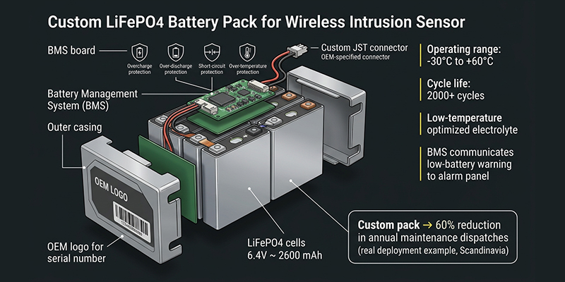
For high-volume production, connector standardization across your product line reduces assembly error. It also simplifies field replacement. Your service teams can work with a single part number. Custom packs are built to your connector specification from day one.

OEM Labeling and Traceability

For managed security service providers deploying thousands of units, battery traceability matters for warranty claims, maintenance scheduling, and regulatory documentation. Custom packs can be built with your branding, serial number labeling, and lot-level traceability built into the supply chain.

A Real Deployment Example

A European security system integrator came to us with a specific challenge. Their wireless PIR sensors and outdoor infrared intrusion sensors were being deployed in remote agricultural perimeters in Scandinavia and Eastern Europe. Standard primary lithium cells were failing within 18 months in cold conditions. The logistics of field replacement across widely distributed rural installations was becoming unsustainable.

We developed a custom LiFePO4 pack for their sensor line: 3.2V nominal, 2,600 mAh, with a low-temperature optimized electrolyte and a miniaturized BMS configured to their panel’s low-battery communication protocol. Operating range: -30°C to +60°C. The result was sensor battery life exceeding 4 years in field conditions, and a 60% reduction in annual maintenance dispatch events. Their field service cost per site dropped significantly in the first full year of deployment.

Custom LiFePO4 battery pack for OEM intrusion sensor and perimeter security system

B2B Procurement Decision Checklist

Before reaching out to a battery supplier for an alarm system project, work through these questions. Your answers will determine the right specification and help you evaluate supplier capability quickly.

Application Layer

  • Am I powering a control panel (backup), a wireless sensor, or both?
  • Is this a new design or a retrofit/replacement procurement?

Environmental Requirements

  • What is the minimum operating temperature in the field?
  • Is the battery installed indoors (panel cabinet) or outdoors (perimeter sensor enclosure)?
  • What IP rating does the enclosure achieve? Does the battery need to match?

Performance Requirements

  • What is the required backup duration (hours) at rated load current?
  • What battery life (years) is promised to the end customer?
  • Does the system platform communicate battery health data back to a management interface?

Volume and Supply Chain

  • What is your annual unit volume? (Determines MOQ feasibility for custom packs)
  • Do you require OEM labeling, serial number traceability, or custom connectors?
  • What certification marks are required for your target market?

Total Cost of Ownership

  • Have you calculated the total field replacement cost over a 5-year deployment life for standard batteries versus a custom long-cycle solution?
  • What is the cost of a single technician dispatch to your average field site?

If you find yourself uncertain about several of these questions, that’s normal — and it’s exactly what a battery engineering consultation is designed to resolve before you commit to a specification.

How Himax Electronics Supports Security System Manufacturers

At Himax Electronics, we have built our battery engineering capability specifically around the requirements of industrial and commercial OEM clients — not consumer retail. Our perimeter security and intrusion sensor battery solutions are developed through a structured engineering engagement, not a catalog lookup.

Our process begins with a technical review of your device’s power architecture, load profile, and environmental operating conditions. From there, our pack development team designs the cell configuration, BMS parameters, and form factor to match your specification. Samples are validated against your system before any production commitment.

For alarm system applications specifically, we offer:

  • LiFePO4 and Li-ion custom packs for wireless intrusion sensors, PIR detectors, and perimeter beam sensors

  • 12V backup battery solutions for control panels, with AGM and LiFePO4 options depending on cycle life and temperature requirements

  • BMS-integrated packs with configurable low-battery thresholds and communication interfaces

  • Operating range -20°C to 60°C as standard, with extended low-temperature electrolyte options for extreme environments

  • 9-tier safety testing protocol covering overcharge, over-discharge, short circuit, crush, thermal abuse, and vibration

  • Full certification support: UN38.3, IEC 62133, CE, UL — coordinated through our in-house compliance team

  • OEM labeling, custom connectors, and lot traceability for managed service deployments

Our intelligent BMS design extends effective battery life by up to 30% compared to standard pack configurations in the same form factor. That is a measurable difference in field maintenance frequency and total deployment cost.

We work with security hardware manufacturers, alarm panel OEMs, and large-scale integrators across Europe, North America, and Southeast Asia. If your organization is evaluating battery options for a new product line, a retrofit procurement, or a custom development project, we are set up to support that engagement from initial specification through to volume production.

Final Thoughts: Power Is Not a Secondary Specification

The performance of your alarm system — in the field, over years of deployment — is ultimately constrained by the reliability of its power source. A sensor that goes dark because of a failed battery is indistinguishable from a sensor that was never installed. The security gap is the same.

For B2B buyers and OEM manufacturers, the question is not simply “which battery fits the slot?” It is: What power solution, designed for our specific application environment and deployment scale, will minimize maintenance costs, meet certification requirements, and protect the reliability promise we have made to our customers?

If you have read this far, you are asking the right questions. The next step is a direct conversation with an engineer who can map your requirements to a validated solution.

Ready to discuss a custom battery solution for your alarm system product line?

Contact our engineering team at Himax Electronics to request a technical consultation and sample evaluation. We respond to all OEM inquiries within 24 hours.

Related resource: Perimeter Security & Intrusion Sensors Battery Solutions — Himax Electronics

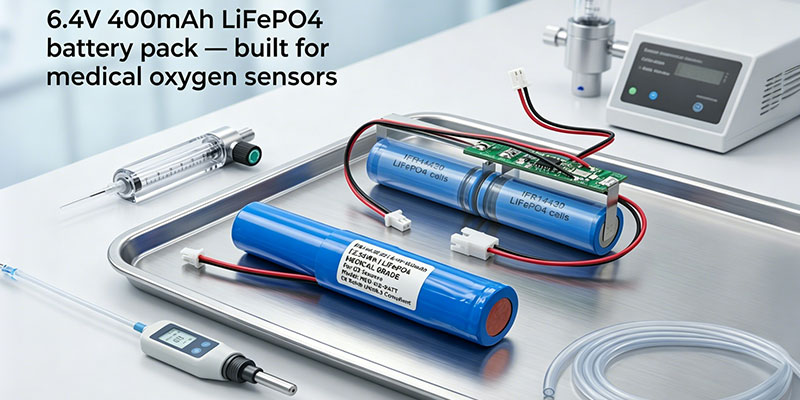
medical oxygen sensor battery LiFePO4 6.4V 400mAh pack Himax electronics

Author: Joan Li — Battery Engineer, Custom Pack Development | Himax Electronics Category: Technical Blog / Battery Engineering / Medical Applications

Introduction: When a Dead Battery Is Not an Option

Imagine a portable medical oxygen sensor going dark mid-shift in a busy ICU — or a wireless O2 monitoring node dropping offline during a home health visit. For medical device manufacturers, battery failure is not just an inconvenience. It is a patient safety risk, a warranty liability, and, in regulated markets, a compliance problem.

If you are currently specifying a power source for a medical oxygen sensor, a pulse oximeter, or a portable respiratory monitor, you already know that not every lithium battery belongs in a clinical setting. The chemistry, the protection circuit, the thermal behavior, the cycle life — all of it matters in ways that simply do not apply to consumer electronics.

This guide is written from the bench, not the marketing department. I am going to walk you through every parameter that affects your purchasing decision for the Himax LiFePO4 6.4V 400mAh battery pack (Model 110-00001) — and explain, in plain engineering terms, why each one matters for oxygen sensor medical applications.

Why LiFePO4 Is the Right Chemistry for Medical O2 Sensor Devices

Before diving into specifications, it is worth being direct about chemistry selection. OEM procurement teams frequently ask why we recommend LiFePO4 over standard NMC or LCO lithium-ion for medical o2 sensor products. The answer comes down to three factors that are non-negotiable in clinical and near-clinical environments.

Thermal stability. LiFePO4 cells have a significantly higher thermal runaway threshold than NMC chemistry. The phosphate-oxygen bond in the cathode is chemically stable, which means the cell does not release oxygen during breakdown the way NMC cells do. For a device strapped to a patient or carried in a clinical bag, this matters.

Flat discharge curve. LiFePO4 delivers a remarkably stable voltage output — around 3.2V per cell — for the vast majority of its discharge cycle before dropping off sharply at end-of-charge. For sensors that require consistent operating voltage to maintain measurement accuracy, this is a genuine engineering advantage over chemistries that slope continuously from full to empty.

Cycle life. Standard NMC batteries are commonly rated for 300–500 cycles before meaningful capacity loss. LiFePO4 routinely reaches 1,000–2,000+ cycles. For medical devices that are charged daily, that is the difference between replacing batteries once a year versus once every five or six years.

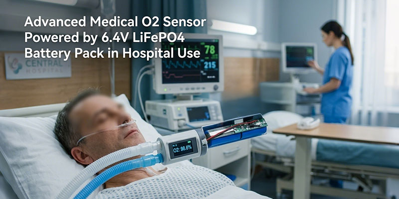
The 2S1P configuration of this pack — two 3.2V cells in series — gives you a nominal 6.4V output at 400mAh capacity, ideal for powering low-power medical sensor platforms where both stable voltage and compact form factor are required.

oxygen sensor medical device powered by 6.4V LiFePO4 rechargeable battery pack

Complete Technical Specification Breakdown

This section is the specification data you need to complete a BOM entry, submit to your regulatory team, or pass to your mechanical engineer for integration planning. All values are sourced directly from Himax specification document HLFGB02 0A40-1527, Revision A2.

Cell-Level Specifications

The individual cells used in this pack are LiFePO4 format 14430, rated at 400mAh nominal capacity (minimum 370mAh) with a nominal cell voltage of 3.2V. Internal impedance is ≤60mΩ per cell, and cell dimensions are a maximum of 14.35mm × 43mm with an approximate weight of 14.5g per cell.

Battery Pack Electrical Parameters

Parameter Value
Pack Configuration 2S1P
Nominal Voltage 6.4V
Nominal Capacity 400mAh
Minimum Capacity 370mAh
Energy 2.56Wh
Charge Voltage 7.2V
Charge Method CC/CV
Standard Charge Current 0.08A
Max. Charge Current 0.4A
Standard Discharge Current 0.08A
Max. Continuous Discharge Current 0.5A
Discharge Cut-off Voltage 5.0V
Cycle Life 2,000 cycles
Pack Internal Impedance ≤350mΩ

Physical Specifications

Parameter Value
Dimensions Approx. 86.7 × 17.6 × 14.8mm
Weight Approx. 32g
Output Wire AWG28, (30+5)±3mm
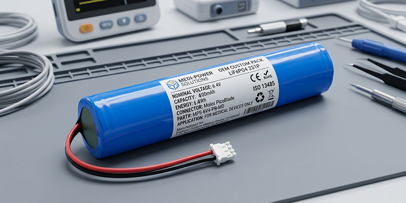
Output Connector Molex PicoBlade 1.25mm, 2-pin

The Molex PicoBlade 1.25mm connector is a practical choice for medical device integration — it is a widely adopted, space-efficient connector that mates reliably with standard PCB footprints used across portable medical platforms.

Operating and Storage Temperature Ranges

Condition Temperature Range
Charging 0°C to 45°C
Discharging -20°C to 60°C
Storage -10°C to 45°C

For products deployed in ambulance environments, outdoor monitoring scenarios, or cold-storage adjacent settings, the -20°C discharge lower limit is a meaningful advantage over standard lithium-ion packs.

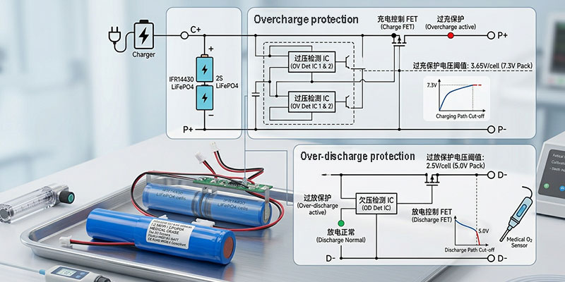
medical o2 sensor battery PCM protection circuit overcharge over-discharge diagram

Electrical Performance Specifications

The electrical performance data below reflects test results under standard conditions: 20±5°C ambient temperature, 65±20% relative humidity.

Open-Circuit Voltage: ≥6.6V, measured within 24 hours of standard charge.

Battery Capacity Retention (Room Temperature): ≥95% of rated capacity after standard charge and 30-minute rest at 20±5°C.

Cycle Life Performance: ≥80% of initial capacity retained after 2,000 charge-discharge cycles at standard conditions. For a device charged once daily, this represents over five years of use before meaningful degradation.

Charge Retention (28-Day Storage): ≥95% of capacity retained after 28 days of storage at 20±5°C following standard charge. This supports products that may sit in warehouse inventory or hospital storage before deployment.

High-Temperature Performance (55°C): ≥90% capacity delivery after a 2-hour soak at 55°C, then discharged at standard rate. Relevant for devices used in warm clinical environments or transported in vehicles.

Low-Temperature Performance (-10°C): ≥50% capacity delivery after a 4-hour soak at -10°C. Cold-chain transport and outdoor monitoring scenarios should account for this in device power budgeting.

PCM Protection Circuit: The Safety Layer Your Compliance Team Will Ask About

Every battery sold into a medical-adjacent application should have a protection circuit module (PCM). The Himax pack integrates a PCM with the following parameters, all verified against the specification document:

Overcharge Protection

  • Detect voltage: 3.65V ±0.025V per cell
  • Delay time: 0.5–1.5 seconds
  • Reset voltage: 3.45V ±0.05V per cell

Over-Discharge Protection

  • Detect voltage: 2.0V ±0.08V per cell
  • Delay time: 70–200ms
  • Reset voltage: 2.5V ±0.1V per cell

Over-Current Protection

  • Detect current: 2A ±0.5A
  • Delay time: 5–40ms
  • Reset: Release load

Short-Circuit Protection

  • Condition: External short circuit detection
  • Reset: Release load

PCM Resistance: ≤200mΩ

From an OEM perspective, the critical question is whether these protection parameters are compatible with your device’s charging circuit and BMS architecture. If your device uses a host-side charger operating at 7.2V with a current limit of 0.4A or less, this pack’s PCM is designed to work within that window. For applications with tighter current control requirements or non-standard charge profiles, contact our engineering team before committing to volume.

Safety and Mechanical Testing: What This Pack Has Been Through

Regulatory submissions for medical devices — whether CE marking in Europe or FDA clearance in the United States — require documented evidence that the battery does not create a hazard under foreseeable use and misuse conditions. This pack has been tested against GB/T18287-2013, UL1642, and CE61960 technology standards.

Crush Test: Force applied by a 32mm-diameter hydraulic piston to 13kN. Result: No fire, no explosion.

Drop Test: Dropped from 1 meter onto concrete in two orientations, twice each. Result: No explosion, no fire, no smoke.

Vibration Test: Simple harmonic motion at 1.6mm amplitude, swept from 10Hz to 55Hz at 1Hz per minute, applied for 30 minutes per axis across all three XYZ axes. Result: No leakage, no fire, no explosion.

Cell-Level Overcharge Test: Constant current at 1C to 4V per cell, then constant voltage hold until current reaches zero. Result: No explosion, no fire.

Cell-Level Short-Circuit Test: External short applied (≤50mΩ load) until voltage drops below 0.1V or cell surface temperature returns to ambient ±10°C. Result: No explosion, no fire, cell surface temperature below 150°C.

Heating Test: Cell heated in circulating air oven at 5±2°C/minute to 130°C, held for 30 minutes. Result: No explosion, no fire.

For procurement teams supporting FDA 510(k) submissions or CE technical files, these test results can be referenced in the battery section of your risk management documentation under ISO 14971.

Application Landscape: Where This Battery Fits in Medical Oxygen Sensing

The 6.4V 400mAh form factor was not chosen arbitrarily. It sits at the intersection of several design constraints that define portable oxygen sensor medical platforms: low continuous current draw, compact footprint, multi-day or multi-shift runtime, and the need to survive routine handling in clinical environments.

Here is where procurement teams most commonly deploy this pack:

Pulse Oximeters and SpO2 Monitors Handheld and wrist-mounted SpO2 monitors operate at low continuous power — typically well within the 0.5A maximum discharge current of this pack. The 2.56Wh energy capacity supports extended monitoring sessions, and the compact 86.7mm × 17.6mm × 14.8mm form factor integrates cleanly into handheld device enclosures.

Medical Oxygen Sensor Modules Dedicated oxygen sensor medical modules — including electrochemical O2 sensors used in anesthesia machines, ventilators, and gas monitors — require stable, clean power. The flat discharge profile of LiFePO4 reduces the need for additional voltage regulation circuitry in sensor analog front ends, which is a real BOM cost advantage.

Medical O2 Sensor Nodes in Wireless Monitoring Systems In hospital ward monitoring installations, distributed medical o2 sensor nodes that report to a central station need batteries that last through a full clinical shift without creating hot-swap logistical burdens. The 2,000-cycle rating means these nodes can be recharged nightly for years before battery replacement becomes a maintenance concern.

Portable Respiratory Function Analyzers Spirometers, peak flow meters, and portable capnography units in the 6V operating range benefit from the pack’s stable voltage and light weight. At approximately 32g, it does not meaningfully affect the ergonomics of handheld devices.

Home Health and Remote Patient Monitoring Devices Devices leaving the hospital environment face less controlled charging conditions. The robust over-discharge protection (2.0V detect with reset at 2.5V) prevents deep discharge damage in scenarios where patients or caregivers may not charge devices on a strict schedule.

Telemedicine Sensor Platforms and Wearable Vital Sign Monitors Low-power wireless vital sign sensors that integrate oxygen sensing, heart rate, and temperature monitoring in a single compact unit benefit from the pack’s combination of small size, adequate energy density, and safe chemistry.

LiFePO4 battery OEM custom pack 2S1P Molex PicoBlade connector medical device application

OEM and Bulk Procurement: What to Verify Before You Commit to Volume

If you are sourcing this battery in quantity for production integration, here are the five technical verification checkpoints that matter most before purchase order placement.

  1. Connector CompatibilityVerify that your device’s PCB connector footprint matches the Molex PicoBlade 1.25mm 2-pin mating connector. If you require a different connector — JST PH 2.0, Hirose DF13, or a custom wire harness termination — that is a customization we can accommodate. Specify this at the RFQ stage.
  2. Charge Voltage CompatibilityYour device’s charging circuit must be configured to charge to 7.2V (±tolerance as specified by your charger IC). Charging to a higher voltage will trigger PCM overcharge cutoff on every cycle, reducing effective capacity and accelerating aging.
  3. Maximum Continuous Current MarginThe pack is rated for 0.5A maximum continuous discharge. If your device has peak current draws above this threshold — motors, pumps, high-power RF transmitters — validate your peak load against the PCM over-current trip point of 2A ±0.5A and ensure your duty cycle stays within the continuous rating.
  4. Temperature Range ValidationIf your product will be stored or operated outside the ranges listed in this specification, contact us before committing to this SKU. Operating the pack outside specified temperature limits will void the warranty and may affect regulatory compliance.
  5. Shipment Voltage and Pre-Integration StorageBatteries ship at 30–70% state of charge (SOV: 6.4–6.6V) as required for safe transport. If your assembly line will store batteries for more than three months between receipt and integration, plan for a top-up charge cycle before installation. Long-term storage at low state of charge accelerates capacity fade.

Delivery, Packaging, and Shipment Standards

Each pack is verified for voltage, internal resistance, and protective circuit function before shipment. Packs are transported at approximately 30–70% charge state in protective packaging designed to prevent mechanical stress during transit.

The packaging specification prohibits co-shipment with metal objects and requires protection from direct sunlight, moisture, severe vibration, and compression. Transport modes include road, rail, sea, and air freight under applicable dangerous goods regulations for lithium batteries (UN 3481).

If you receive a shipment and notice any abnormal odor — electrolyte smell in particular — do not use the affected units. Document and report the condition for warranty processing.

Customization Capabilities: When Standard Is Not Enough

The 110-00001 is a standard catalog pack. However, many medical device programs require something that does not exist off the shelf. Himax’s custom pack development capability covers:

  • Connector type and orientation— including board-mount, right-angle, and custom wire harness terminations
  • Wire length and gauge— tailored to your cable routing and connector placement within the enclosure
  • Pack dimensions— within the constraints of the 2S1P 14430 cell configuration
  • Capacity adjustment— alternative cell capacities in the 14430 form factor
  • Label and marking— including custom branding, UL file references, and regulatory marking for your target markets

Custom development projects begin with an NDA and technical requirements document. Sample lead times for custom configurations are typically 3–5 weeks, with production tooling complete within 8–12 weeks depending on mechanical complexity.

Warranty and Quality Assurance

This battery pack carries a one-year warranty from the date of shipment. Himax will replace any unit where a defect is attributable to the manufacturing process. Warranty coverage does not extend to damage resulting from misuse, including charging outside specified parameters, mechanical abuse, immersion, or operation outside specified temperature ranges.

For quality-critical production programs, incoming inspection protocols should include voltage verification (target: 6.4–6.6V), impedance measurement (≤350mΩ at pack level), and a functional check of the protective circuit response to overcharge or over-discharge stimulus.

Safe Operation: A Note for Device Integration Teams

The following operating rules are non-negotiable from a safety and warranty standpoint. They are reproduced here for integration engineers who may be writing device-level operating instructions.

  • Use only a LiFePO4-compatible charger rated for 7.2V / ≤0.4A. Do not use a generic lithium-ion charger calibrated for 8.4V (2S NMC).
  • Do not continuously charge the pack for more than 8 hours.
  • Do not reverse polarity. The connector is keyed to prevent this, but wire harness errors during custom integration are possible — verify polarity before applying power.
  • Do not expose the pack to temperatures above 60°C during discharge or 45°C during charging.
  • For storage longer than three months, maintain the pack at approximately 50% state of charge and store between -10°C and 45°C.
  • Do not solder directly to the pack terminals or pierce the cells.

Summary: The Six Reasons Medical Device Manufacturers Choose This Pack

If you have read this far, you are likely evaluating this battery for a real program. Here is the short version for your decision brief:

  1. Chemistry match— LiFePO4 is the safest lithium chemistry available for medical-adjacent applications, with high thermal stability and no oxygen-releasing breakdown mechanism.
  2. Stable 6.4V platform— The 2S1P configuration delivers consistent voltage across 80%+ of the discharge curve, reducing downstream regulation requirements.
  3. 2,000-cycle rating— Five-plus years of daily charging without significant capacity loss, reducing lifetime cost and field service burden.
  4. Certified to GB/T18287-2013, UL1642, CE61960— The safety test documentation exists and is available to support your regulatory submission.
  5. Compact and light— 86.7mm × 17.6mm × 14.8mm, 32g, with a Molex PicoBlade connector for clean PCB integration.
  6. Customizable— If the standard pack does not fit your enclosure or connector requirements, we can build to your specification.

Talk to an Engineer Before You Place Your Order

Every medical device program is different. Before you commit to volume, I encourage you to send us your power requirements, connector specification, and operating environment parameters. We will validate that this pack — or a custom variant — is the right fit for your application, and we can provide sample units for your engineering validation testing.

Contact Himax Electronics:

  • Website: himaxelectronics.com
  • Tel: +86 (0)755-25629920
  • Address: Building B, Nantong Avenue No.5, Tongle Community, Baolong Street, Longgang, Shenzhen, China

— Joan Li, Battery Engineer, Custom Pack Development, Himax Electronics

Specification data referenced in this article is sourced from Himax technical document HLFGB02 0A40-1527, Revision A2, dated September 20, 2024. All performance specifications are subject to the test conditions described in that document.

12V-lifepo4-battery-pack

The cathode chemistry you choose defines everything downstream — cycle life, thermal ceiling, energy density, cost per kWh, and the safety margin you’re engineering around. After years of working alongside cells from multiple chemistries across EV, stationary storage, and industrial applications, the differences stop being abstract and become very concrete very fast.

This article breaks down the three cathode chemistries that dominate the market today: Lithium Iron Phosphate (LiFePO4 / LFP), Nickel Manganese Cobalt Oxide (NMC), and Nickel Cobalt Aluminum Oxide (NCA). We’ll cover the electrochemistry, real-world performance tradeoffs, safety characteristics, cost dynamics, and which applications each chemistry genuinely suits.

A Quick Note on Why Cathode Chemistry Matters So Much

In a lithium-ion cell, the cathode is the rate-limiting component. It dictates nominal voltage, theoretical capacity, thermal stability, and the degradation pathways that determine how long a pack lasts under real operating conditions. The anode — typically graphite across all three chemistries — matters too, but the cathode is where the key engineering tradeoffs live.

Understanding these tradeoffs isn’t just academic. Choosing the wrong chemistry for your application means either leaving performance on the table or designing around failure modes you didn’t fully account for.

LiFePO4 (LFP): The Safety-First Workhorse

The Electrochemistry

LiFePO4 uses an olivine crystal structure for its cathode material. The strong covalent P–O bond within the phosphate (PO₄³⁻) polyanion stabilizes the structure even at high temperatures and states of charge — this is the chemical root of LFP’s exceptional thermal stability.

Nominal voltage: ~3.2–3.3V per cell
Theoretical specific capacity: ~170 mAh/g
Practical energy density: 90–160 Wh/kg at the cell level; 200–270 Wh/L volumetric

The flat discharge curve — characteristic of LFP — is both an advantage and a complication. Voltage sits nearly constant between roughly 20% and 80% state of charge (SOC), which means battery management systems (BMS) must rely on coulomb counting rather than open-circuit voltage to estimate SOC accurately. For systems running long partial-charge cycles, this requires more sophisticated BMS design.

Cycle Life and Calendar Aging

This is where LFP separates itself. Well-designed LFP cells routinely deliver 3,000–6,000 full charge-discharge cycles to 80% capacity retention at standard temperatures. Some premium cells marketed for grid storage are validated beyond 6,000 cycles at controlled depths of discharge.

Calendar aging is also favorable. The olivine structure resists phase transitions that degrade other cathode materials, and LFP doesn’t suffer the same transition-metal dissolution issues that accelerate capacity fade in nickel-rich chemistries at elevated temperatures.

Thermal Stability: The Real Differentiator

LFP’s safety advantage comes from thermodynamics, not just engineering controls. The onset of exothermic reactions in LFP cells under abuse conditions (thermal runaway triggering) is around 270–310°C — significantly higher than NMC or NCA. The energy released during thermal runaway is also substantially lower, and critically, LFP does not release oxygen during decomposition. That last point matters enormously: without oxygen release, self-sustaining combustion is far less likely.

For applications where thermal runaway propagation in a multi-cell pack could be catastrophic — residential energy storage, marine, aviation-adjacent, high-density data center UPS — this is a decisive consideration.

Where LFP Falls Short

Energy density. At the cell level, LFP’s 3.2V nominal voltage and lower practical capacity translate directly to larger, heavier packs for equivalent energy storage. In EV applications, this means either longer charge times, shorter range, or heavier vehicles — tradeoffs that matter at scale.

LFP also has reduced performance at low temperatures. Below 0°C, internal resistance rises sharply, and charging below freezing without proper thermal management risks lithium plating on the anode, accelerating degradation.

Typical Applications

  • Grid-scale and residential stationary energy storage (BESS)
  • Commercial EVs and buses where weight is less critical than longevity
  • Industrial forklifts and material handling equipment
  • Marine and off-grid power systems
  • Any application with long service life requirements and moderate energy density needs
    deep-cycle-12v-24v-48v-lifepo4-battery-pack

NMC (Nickel Manganese Cobalt Oxide): The Balanced All-Rounder

The Electrochemistry

NMC cathodes use a layered transition metal oxide structure where nickel, manganese, and cobalt occupy the transition metal sites. Each element contributes differently: nickel provides high capacity, manganese contributes structural stability, and cobalt improves rate capability and reduces cation mixing.

The ratio of these elements — expressed as NMC 111, NMC 532, NMC 622, NMC 811 and so on — is not cosmetic. Increasing nickel content (moving toward NMC 811 and beyond) increases specific capacity but also increases sensitivity to overcharge and thermal instability. This is the central engineering tension driving NMC formulation research today.

Nominal voltage: ~3.6–3.7V per cell
Theoretical specific capacity: ~200 mAh/g (NMC 111) to ~275+ mAh/g (high-Ni variants)
Practical energy density: 150–300 Wh/kg at cell level, depending on formulation

The NMC Spectrum

NMC 111 (equal parts Ni, Mn, Co) is the most chemically stable formulation — moderate capacity, good cycle life, manageable thermal behavior. It’s largely been superseded in high-performance applications but remains in use where balance and reliability are paramount.

NMC 622 (60% Ni, 20% Mn, 20% Co) became widely adopted in EV applications through the 2010s, offering a meaningful step up in energy density with acceptable stability. Most mainstream EV platforms through 2020–2022 used variants of 622 or similar compositions.

NMC 811 (80% Ni, 10% Mn, 10% Co) is the current high-performance standard. The energy density advantage is real — cells exceeding 250 Wh/kg are achievable — but the tradeoffs are real too. Higher nickel content means more reactive surfaces, greater sensitivity to moisture during manufacturing, more complex electrolyte requirements, and a tighter thermal management window.

Single-crystal NMC (also called monocrystalline) is a structural modification rather than a new chemistry — NMC particles are grown as single crystals rather than polycrystalline aggregates. This reduces micro-cracking during cycling, improving cycle life substantially at equivalent Ni content. Many current-generation premium EV cells use single-crystal NMC 811 or high-nickel variants.

Cycle Life

NMC cycle life varies significantly with formulation and operating conditions. NMC 111 can achieve 1,500–2,000+ cycles to 80% retention under moderate conditions. NMC 811 in real-world cycling typically delivers 500–1,500 cycles depending on depth of discharge, temperature, and charge rate. Extended calendar aging at high SOC accelerates capacity fade.

One practical implication: NMC packs for EV applications are often managed to operate between 20–80% SOC in daily use to protect cycle life, which partially offsets the raw energy density advantage.

Thermal Characteristics

NMC’s thermal stability decreases as nickel content increases. Exothermic decomposition begins at roughly 200–250°C for lower-nickel formulations and can drop below 200°C for NMC 811. Critically, NMC cathodes release oxygen during thermal decomposition, which can feed combustion if a separator breach has already occurred.

This doesn’t make NMC inherently unsafe — modern cell design, BMS electronics, and thermal management systems (ATMS) in well-engineered packs manage these risks effectively. But the safety envelope is tighter than LFP, and pack-level design must account for thermal propagation paths.

Typical Applications

  • Passenger EVs (dominant chemistry in most current-generation long-range vehicles)
  • Consumer electronics
  • Power tools
  • E-bikes and light electric mobility
  • Portable energy storage
  • Any application where energy density and weight are primary constraints

NCA (Nickel Cobalt Aluminum Oxide): The High-Performance Specialist

The Electrochemistry

NCA uses aluminum rather than manganese as the third transition metal. The aluminum isn’t electrochemically active — it doesn’t participate in lithium intercalation — but it provides structural stability, particularly at high states of charge and elevated temperatures. This allows NCA to push nickel content even higher than most NMC formulations, typically 80%+ nickel.

Nominal voltage: ~3.6–3.65V per cell
Theoretical specific capacity: ~200–280 mAh/g
Practical energy density: 200–300+ Wh/kg at cell level

Tesla’s 18650 and 2170 cylindrical cells (produced with Panasonic) use NCA chemistry and have been central to the high-energy-density strategy that made long-range EVs commercially viable earlier than most competitors.

Performance Characteristics

NCA’s standout attributes are raw energy density and power capability. At the top end, NCA cells can deliver the highest practical specific energy of the three chemistries. They also perform well in high-power discharge scenarios, making them suitable for performance-oriented EV applications where acceleration and sustained high-current output matter.

Cylindrical cell formats — the 18650, 2170, and the newer 4680 — work particularly well with NCA chemistry, and the manufacturing maturity behind large-format cylindrical NCA cells is substantial.

Cycle Life and Degradation

NCA cycle life is generally lower than NMC 622 and considerably lower than LFP. 500–1,000 cycles to 80% retention is a reasonable expectation for high-performance NCA cells under real-world conditions, though chemistry improvements and single-crystal approaches are extending this. Calendar aging is also more pronounced than LFP.

This is manageable in EV applications through BMS strategies (SOC windowing, temperature-controlled charging) and over-provisioning — building in buffer capacity so that even after significant degradation, the usable range remains acceptable to the owner.

Thermal and Safety Profile

NCA has the narrowest thermal safety window of the three. Exothermic decomposition can begin at temperatures below 180°C in some formulations, and oxygen release during thermal runaway is significant. Pack-level thermal management for NCA requires robust cooling, well-characterized separator materials, and careful cell-to-cell spacing or thermal barrier design.

Tesla’s approach to NCA — large numbers of small cylindrical cells with individual fuse elements and sophisticated thermal management — is a deliberate design response to these characteristics. Thousands of small cells with fuses allows individual cell failures to be electrically isolated before they propagate thermally, at the cost of significant pack complexity.

Typical Applications

  • High-performance and long-range passenger EVs
  • Aerospace and high-value portable electronics
  • Applications where maximum energy density at the cell level is the overriding priority
  • Professional tools and equipment with short duty cycles

Direct Technical Comparison

Parameter LiFePO4 (LFP) NMC (varies by grade) NCA
Nominal cell voltage 3.2–3.3V 3.6–3.7V 3.6–3.65V
Practical specific energy 90–160 Wh/kg 150–300 Wh/kg 200–300+ Wh/kg
Cycle life (to 80%) 3,000–6,000+ 500–2,000+ 500–1,500
Thermal runaway onset ~270–310°C ~200–250°C ~150–180°C
Oxygen release on thermal runaway No Yes Yes
Cobalt content None Moderate (decreasing) Moderate
Low-temperature performance Poor Moderate Moderate
Calendar aging Low Moderate Higher
Relative cost (per kWh) Low–Moderate Moderate Moderate–High
SOC estimation complexity Higher (flat OCV) Lower Lower
Primary application fit Stationary, commercial EV Passenger EV, consumer electronics High-performance EV, aerospace

The Cost Dimension

Chemistry costs are not static — they track commodity metal prices, manufacturing volumes, and supply chain geography, all of which have shifted substantially over the past five years.

LFP has become dramatically cheaper as Chinese manufacturers have achieved massive scale. Current cell-level costs for competitive LFP cells are approaching or below $60–70/kWh in volume, making it increasingly attractive even for applications where energy density had previously justified NMC.

NMC costs are tied to cobalt and nickel prices. The industry trend toward higher nickel content (reducing cobalt) is partly an energy density play and partly a supply chain risk mitigation strategy — cobalt supply is concentrated geographically and subject to price volatility. NMC 811 and NMCA (NMC with aluminum) formulations reduce cobalt use substantially.

NCA costs reflect high nickel content and the quality controls required for consistent high-performance cell production. Volume manufacturing in large cylindrical form factors has driven costs down considerably from early benchmarks, but NCA generally commands a premium over LFP for equivalent capacity.

What’s Changing: Technology Trends Worth Watching

LFP + silicon anode is an active area of development. The energy density gap between LFP and NMC is the primary knock against LFP. Adding silicon (or silicon-dominant) anodes increases cell capacity without changing cathode chemistry, potentially narrowing that gap materially.

Cobalt-free NMC variants — including LNMO (lithium nickel manganese oxide) and various NMCA formulations — represent attempts to retain NMC’s performance profile while eliminating or nearly eliminating cobalt dependency. Some are in commercial production; others remain in late-stage development.

Solid-state electrolytes affect all three cathode chemistries differently. Solid-state cells could substantially improve NCA and NMC safety profiles by eliminating the flammable liquid electrolyte, while also potentially enabling higher nickel content without the same thermal management requirements. LFP with solid-state electrolytes is less of a priority given LFP’s already favorable safety profile.

4680 format NCA/NMC cells — the larger cylindrical format pioneered for high-volume EV production — change the pack-level economics significantly. Fewer cells per pack, higher energy per cell, and improved manufacturing integration reduce pack costs independent of cathode chemistry.

Choosing the Right Chemistry: A Practical Framework

There is no universally superior cathode chemistry. The right choice depends on the requirements hierarchy of a specific application:

If your primary constraint is safety and longevity — and especially if thermal runaway propagation in a dense pack is a failure mode you cannot accept — LFP is the defensible choice. Residential energy storage, marine, aviation-adjacent, and any application where fire risk is catastrophic all benefit from LFP’s wider thermal margin and absence of oxygen release.

If your primary constraint is energy density at a competitive system cost — as in most passenger EV platforms — NMC in its higher-nickel variants (622, 811, single-crystal 811) offers the best current balance of capacity, cost, and reasonable cycle life with good thermal management.

If you are optimizing for maximum performance and have the engineering resources to manage a tighter safety envelope — NCA delivers the highest raw energy density and power capability. The complexity cost is real, and it requires serious investment in BMS sophistication and thermal management design.

Many modern systems don’t make a single-chemistry choice — dual-chemistry packs (LFP base + NMC peak-power buffer) exist in some commercial designs, though they add system complexity.

Final Thoughts

The “which chemistry is best” question is less useful than “which chemistry is best for this load profile, at this temperature range, over this service life, at this cost target.” Battery engineers have understood this for years; it’s increasingly becoming the fluency required at the product and systems integration level too.

What’s changing is that the traditional tradeoffs are softening at the edges. LFP’s energy density disadvantage is narrowing. NMC’s cobalt dependency is shrinking. NCA’s manufacturing challenges are being addressed through format innovation. The competitive landscape in 2025–2026 looks different from 2020, and it will look different again in 2028.

Understanding the electrochemistry behind each choice — not just the spec sheet — is what allows you to anticipate where those trends are heading and make decisions that hold up over a product’s lifetime.

Have questions about cathode chemistry selection for a specific application? Our engineering team works with LFP, NMC, and NCA systems across stationary storage, EV, and industrial segments. Contact us for a technical consultation.

Tags: LiFePO4, NMC, NCA, lithium-ion battery, cathode chemistry, battery technology, energy storage, EV battery, battery comparison, LFP vs NMC, battery engineering


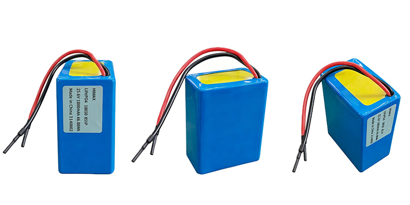
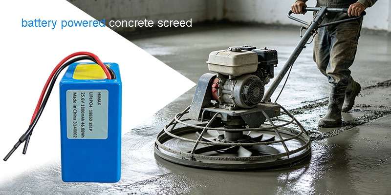
battery powered concrete screed LiFePO4 battery 25.6V 1.8Ah compact battery pack design

I’m Joan, a Battery Engineer at Himax Electronics, specializing in custom battery pack development for demanding OEM applications. Over the past decade, I’ve worked closely with manufacturers who rely on battery powered concrete screed systems—tools that don’t just need power, but need reliable power under extreme conditions.

If you’re a B2B buyer or equipment manufacturer, you already know the reality: traditional power solutions struggle with vibration, weight, and lifecycle limitations. That’s where a well-engineered LiFePO4 battery pack (25.6V 1.8Ah) changes the game.

In this article, I’ll walk you through how we designed a battery solution that can withstand continuous heavy vibration, reduce equipment weight by up to 70%, and extend lifecycle by 5–10×—without overpromising, just solid engineering.

Why Battery Powered Concrete Screed Systems Demand Better Energy Solutions

Concrete screeds are not gentle tools. They operate in one of the harshest environments in construction:

  • Constant high-frequency vibration
  • Dust, moisture, and temperature variation
  • Long continuous working hours
  • Heavy mechanical stress

Traditional power solutions—whether fuel-based or outdated battery systems—often fail in one or more of these areas.

The Core Problems I See

From my work with OEM clients, the biggest challenges include:

  • Power instability under vibration
  • Excessive equipment weight
  • Short battery lifespan and frequent replacements
  • Inconsistent supply quality

A poorly designed battery for a battery powered concrete screed doesn’t just reduce performance—it increases downtime and operational costs.

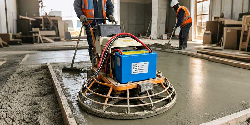
battery powered concrete screed operating on construction site with stable LiFePO4 battery power

Why LiFePO4 Battery Technology Is the Right Choice

Let’s talk chemistry. Choosing the right battery chemistry is the foundation of everything.

For this application, we selected LiFePO4 (Lithium Iron Phosphate), and specifically designed a 25.6V 1.8Ah (8S1P) battery pack.

Key Advantages of LiFePO4

Compared to traditional lithium-ion or lead-acid batteries:

  • Higher thermal stability
  • Longer cycle life (up to 2000 cycles)
  • Better safety performance
  • Stable voltage output under load

This is why I consistently recommend LiFepo4 battery 25.6V 1.8Ah for construction equipment applications.

Real Engineering Data

From the specification:

  • Nominal Voltage:6V
  • Capacity:8Ah
  • Energy:08Wh
  • Max Continuous Discharge:3A
  • Cycle Life:≥2000 cycles
  • Operating Temperature:-20°C to 60°C

This isn’t theoretical performance—this is validated under controlled testing conditions .

Designed for Vibration: Stability Under Extreme Conditions

If there’s one thing that defines a battery powered concrete screed, it’s vibration.

The Engineering Challenge

Most battery packs fail not because of chemistry, but because of:

  • Internal connection fatigue
  • Structural weakness
  • Poor cell fixation

How We Solved It

In this custom pack, we implemented:

  • Reinforced internal structure
  • Optimized cell arrangement (8S1P)
  • Shock-resistant housing design
  • Low internal impedance (≤200mΩ at pack level)

Verified Performance

The battery passed vibration testing:

  • Frequency range: 10–55 Hz
  • Duration: multi-axis testing
  • Result: No leakage, no fire, no explosion

What This Means for You

For manufacturers:

  • Reliable operation in real-world construction environments
  • Reduced failure rates
  • Lower maintenance costs

This is what makes a battery powered concrete screed truly dependable.

Lightweight Design: Up to 70% Weight Reduction

Let’s talk about something every operator cares about—weight.

Traditional systems, especially lead-acid solutions, are heavy. And in construction, weight directly impacts:

  • Operator fatigue
  • Ease of transport
  • Efficiency on-site

Our Solution

The LiFepo4 battery 25.6V 1.8Ah pack weighs approximately:

  • 44 kg

Compared to traditional alternatives, this can reduce system weight by up to 70%.

LiFePO4 battery 25.6V 1.8Ah internal structure designed for vibration resistance in screed equipment

Why It Matters

For your equipment:

  • Easier handling
  • Improved ergonomics
  • Increased productivity

For your business:

  • Better product positioning
  • Competitive differentiation

And yes—your customers will notice the difference immediately.

Long Lifecycle: 5–10× Longer Than Traditional Solutions

Now let’s talk about lifecycle—because this is where the real ROI happens.

The Reality of Battery Replacement

Frequent battery replacement leads to:

  • Higher operational costs
  • Increased downtime
  • Customer dissatisfaction

What We Achieved

With LiFePO4 chemistry:

  • ≥2000 charge/discharge cycles
  • Capacity retention ≥80% after full lifecycle

Compared to traditional batteries:

  • 5–10× longer lifespan

Why This Matters for B2B Buyers

For procurement teams:

  • Lower total cost of ownership
  • Reduced inventory pressure
  • Improved supply chain stability

This is why I often say: choosing the right battery is not a cost—it’s an investment.

Safety: Built Into the Design, Not Added Later

Safety is not a feature—it’s a requirement.

Built-In Protection

The battery pack includes:

  • Overcharge protection (3.75V per cell detection)
  • Over-discharge protection (2.2V threshold)
  • Over-current protection (up to 27A detection)
  • Short-circuit protection

Mechanical Safety

  • Crush test: no fire, no explosion
  • Drop test: stable after 1m drop
  • Thermal test: stable up to high temperatures

All verified under standard testing protocols .

What This Means

For your product:

  • Reduced liability
  • Compliance with industry standards
  • Increased customer trust

A safe battery powered concrete screed is not optional—it’s expected.

Custom Battery Pack Development: My Approach

At Himax Electronics, customization is not just about specs—it’s about solving real problems.

My Process

When I work with OEM clients, I follow a structured approach:

1. Application Analysis
· Load profile
· Operating environment
· Mechanical constraints

2. Cell Selection
· Chemistry (LiFePO4)
· Capacity (1.8Ah)
· Configuration (8S1P)

3. Pack Design
· Structural reinforcement
· Thermal considerations
· Electrical protection

4. Validation Testing
· Electrical performance
· Mechanical durability
· Safety compliance

The Result

A fully optimized LiFepo4 battery 25.6V 1.8Ah tailored for your application.

lightweight battery powered concrete screed solution with long cycle life LiFePO4 battery technology

Supply Chain Stability: What B2B Buyers Actually Need

Let’s be practical. Performance is important—but supply stability is critical.

Common Concerns

  • Inconsistent quality
  • Delivery delays
  • Lack of technical support

Our Approach

  • Standardized manufacturing processes
  • Strict quality control
  • Reliable delivery timelines
  • Direct engineering support

Business Impact

For your company:

  • Predictable production schedules
  • Reduced risk
  • Long-term partnership reliability

This is how we support scalable growth for battery powered concrete screed manufacturers.

Application Value: Real Impact on Equipment Performance

Let’s summarize what this battery solution delivers:

Performance Benefits

  • Stable output under vibration
  • Lightweight design
  • Long lifecycle
  • High safety standards

Business Benefits

  • Lower total cost
  • Improved product reliability
  • Stronger market competitiveness

This is not just a battery—it’s a performance upgrade for your entire system.

Conclusion: The Right Battery Powers Better Equipment

In demanding applications like construction, the difference between average and exceptional performance often comes down to one component—the battery.

A well-designed battery powered concrete screed system powered by a LiFepo4 battery 25.6V 1.8Ah delivers:

  • Stability under extreme conditions
  • Significant weight reduction
  • Long-term reliability
  • Enhanced safety

From my experience, the right battery doesn’t just power your equipment—it strengthens your entire product strategy.

Call to Action

If you’re looking to upgrade your battery powered concrete screed with a reliable, lightweight, and long-lasting power solution, let’s talk.

Contact us today to develop a custom battery pack tailored to your application needs.


Author: Joan Battery Engineer – Custom Pack Development
Published: April 13th, 2026

Energy storage lifepo4 battery

In the rapidly evolving landscape of custom energy storage, the transition from a conceptual schematic to a physical battery pack is fraught with technical challenges. Among these, dimensional tolerance is often the “silent killer” of high-end projects.

This article explores the critical relationship between mechanical constraint systems and electrochemical safety, illustrating why professional-grade custom jigs are not merely accessories, but fundamental requirements for high-precision assembly.

The Case Study: When 1mm Defines Success or Failure

A client recently approached us with a requirement for a specialized lithium battery pack designed to fit into a pre-existing, precision-milled aluminum enclosure. The internal clearance was marginal, leaving virtually zero room for “pack swelling” or assembly misalignment.

  • The Initial Challenge: In the prototype phase, assembly was conducted using standard alignment methods without a project-specific dedicated jig.
  • The Symptom: While electrical characteristics (voltage, impedance, capacity) were flawless, cumulative tolerance errors in nickel-strip welding resulted in a pack that was 2mm widerthan the CAD specification.
  • The Result: The pack could not be inserted into the battery shell without risking mechanical stress on the cells—a major safety hazard.

Root Cause Analysis: Cumulative Tolerance in Manual Assembly

In battery pack assembly, error is cumulative. Without a rigid constraint system, micro-movements aggregate, resulting in a product that fails the “Go/No-Go” gauge test.

The breakdown of tolerance drift typically looks like this:

  1. Cell Variance: Each cell has a diameter tolerance (e.g., ). Aligning 10 cells in a row can theoretically create a 0mm variance.
  2. Adhesive/Insulation: Inconsistent application of barley paper or structural adhesive can add another 5mm.
  3. Welding Displacement: Without a jig, the pressure of the spot-welding needle can cause cells to shift ( to  ) before the weld nugget solidifies.

lifepo4-48v-battery

The Solution: Engineering a Custom Constraint System

Recognizing that manual alignment was insufficient for the client’s specific shell requirements, our engineering team pivoted to a Jig-Based Manufacturing Process.

  1. Precision CNC-Milled Fixtures

We designed a custom assembly jig using high-stability, non-conductive materials (such as POM or Epoxy board).

  • Zero-Tolerance Cavities: Each cell is seated into a CNC-milled pocket that compensates for the maximum allowable cell diameter while enforcing a strict outer boundary.
  • Vertical Compression: The jig applies uniform lateral and vertical pressure, ensuring cells are perfectly planar before the first weld is made.
  1. Specialized Nickel Strip Alignment

Instead of free-handing the nickel tabs, the new jig featured “guide slots” for the nickel strips. This ensures:

  • Current Path Consistency: Every weld point is exactly where the simulation predicted.
  • Structural Compactness: No “overhang” of nickel or solder, keeping the pack’s footprint within the 1mm tolerance threshold.

The Critical Role of Casing Integrity

Modern battery enclosures often utilize ultrasonic welding or high-precision interference fits. Once a shell is sealed, there is no “fixing” an internal error. Forcing a battery pack into a tight shell creates significant risks:

  • Mechanical Stress: Constant pressure on cell walls can lead to internal micro-shorts over time.
  • Thermal Expansion: Batteries naturally expand slightly during charge/discharge cycles. If the initial assembly does not account for this with precise tolerances, expansion can crack the casing or damage the Battery Management System (BMS).

Engineering Insights: Communication is Key to Precision

The most significant takeaway from this case is that Dimensional Specification is just as critical as Amp-Hour Capacity. For clients with high-precision requirements, we recommend the following protocol during the Request for Quote (RFQ) phase:

  • Define “Critical-to-Quality” (CTQ) Dimensions: Don’t just provide the internal dimensions of your box. Define the Maximum Envelope Dimensions (MED) of the battery pack. Our engineers will then work backward to calculate the necessary jig offsets.
  • Discuss Fixturing Early: If your project has a clearance of less than 2mmbetween the pack and the shell, a custom jig is mandatory. We discuss the cost-benefit analysis of jig fabrication upfront to ensure high yield rates.
  • Tolerance Stack-up Analysis: We provide clients with a report that includes cell manufacturer tolerances, shrink-wrap thickness, nickel strip positioning variance, and jig precision.

Technical Summary: Why Choose Jig-Stabilized Manufacturing?

Benefit Description
Repeatability Whether producing 10 units or 10,000, dimensions remain identical.
Safety Eliminates mechanical friction between the pack and the enclosure.
Serviceability Ensures the pack can be extracted for maintenance without damaging the shell.
Optimized Density Reduces wasted space (“slop”), often allowing more capacity in the same volume.

Precise positioning and welding of battery packs

Conclusion

At our facility, we believe that “close enough” is not an engineering term. The failure of a pack to fit into its housing is not just a logistical delay—it is a failure of process control. By investing in custom jigs and rigorous fixture protocols, we ensure that our lithium solutions are as precise as the devices they power.

Are you working on a project with strict dimensional constraints? Contact our engineering team today to discuss your CAD requirements and how our custom fixturing process can guarantee a perfect fit.


solar-lifepo4-battery

In the rapidly evolving world of Lithium-ion power solutions, “compliance” is often the bridge between a successful product launch and a costly logistical nightmare. For many international buyers, navigating the alphabet soup of certifications—IEC, UL, CE, UN38.3—feels like a routine checkbox exercise. However, a recent case study from our engineering department highlights a critical lesson: Compliance is a holistic ecosystem, not a standalone component.


When a battery fails a lab test, the instinct is to blame the cells. But as we recently discovered during an SGS certification process for a long-term client, the “invisible” culprit is often the charger.


The Case Study: The Gap Between IEC 62133 and CE (EMC)


Recently, a client approached us to provide high-performance battery packs and matching chargers for an industrial application. The initial brief was clear: the units needed to pass IEC 62133 testing via SGS—the gold standard for battery safety.


We optimized the battery protection circuit (PCM) and cell selection to meet these safety rigorous standards. However, midway through the process, the client’s regulatory requirements shifted to include CE marking, which necessitates compliance with the Electromagnetic Compatibility (EMC) Directive.


The result? The system failed the EMC test. While the margin of failure was incredibly slim—a minor deviation in radiated emissions—the consequences were significant:


Project Delays: The testing timeline was pushed back by weeks.


Additional Costs: Re-testing fees and lab overheads added unexpected strain to the budget.


Engineering Re-work: We had to backtrack to shield the charger’s internal circuitry to dampen the interference.


This scenario could have been avoided if the full scope of the “End-Product” certification was defined at the quotation stage.

lifepo4-48v-battery

Understanding the Difference: Safety vs. Compatibility

To prevent these delays, it is vital to understand what these tests actually measure and why they cannot be treated as interchangeable.


  1. IEC 62133: The Safety Guardrail

IEC 62133 focuses almost exclusively on Physical and Chemical Safety. The lab subjects the battery to “torture tests”—crush, vibration, thermal abuse, and overcharging—to ensure the battery doesn’t catch fire or explode. It is about the integrity of the lithium chemistry and the protection board.


  1. CE & EMC: The “Good Neighbor” Policy

The CE mark, specifically the EMC portion (EN 61000 series), isn’t looking at whether the battery is “safe” in a fire-safety sense. Instead, it measures Electromagnetic Interference (EMI). It asks: Does this device emit “noise” that will interfere with other electronics (like a nearby radio or medical equipment)?


Chargers are notorious for failing EMC tests. Because they use switching power supplies (SMPS) to convert AC to DC, they generate high-frequency electrical noise. If the charger isn’t specifically designed with high-quality filters and shielding, it will fail the CE test—even if the battery itself is perfect.


The Domino Effect: Why “Small Deviations” Matter in Lab Testing

In our recent case, the deviation was “very small.” In a real-world scenario, that tiny amount of noise wouldn’t affect the product’s performance. However, accredited labs like SGS, Intertek, or TÜV operate on a binary Pass/Fail system.


A 1dB deviation over the limit is as much a “Fail” as a 50dB deviation. Once a failure is recorded, the lab requires:


A formal “Failure Analysis Report.”


Modified samples (Hardware changes).


A complete re-test of the failed parameters.


This “Domino Effect” eats away at your “Time-to-Market” (TTM), which is often the most valuable asset in the tech industry.


The “System-Level” Approach: Why Early Disclosure is Key

At our factory, we don’t just manufacture batteries; we engineer power systems. When you provide us with the exact list of certifications required for your target market at the start, we can adjust the following details before the first sample ever leaves our floor:


Charger Component Selection: We can opt for premium capacitors and inductors that naturally suppress EMI.


Shielding: We can add copper foil or specialized coatings to the internal housing of the charger or the battery casing.


PCB Layout: Our engineers can optimize the trace routing on the protection board to minimize “antenna effects” that broadcast noise.


Pre-Testing: We can perform in-house “pre-compliance” scans to ensure the 99% success rate when the units hit the official SGS lab.


A Checklist for Global Battery Procurement

To ensure your next project moves from “Prototype” to “Market” without friction, we recommend following this technical checklist when requesting a quote:


List Every Target Market: Are you selling in the EU (CE), USA (UL/FCC), Japan (PSE), or Australia (RCM)? Each has different EMC and safety thresholds.


Define the Test Standard Early: Don’t just say “I need a certificate.” Specify if you need IEC 62133 (Safety), EN 55032 (EMC for Multimedia), or EN 60601 (Medical).


Specify the “System” Testing: Will the battery be tested inside your device, or as a standalone component with its charger? Lab results vary wildly depending on how the system is grounded.


Allow for “Engineering Margin”: Low-cost, “budget” chargers rarely leave any margin for EMC testing. If you need certification, be prepared to invest in a “Certified Grade” charger.


Conclusion: Partnership Over Procurement


The relationship between a buyer and a battery factory should not be a simple transaction; it should be a technical partnership. The recent EMC failure we experienced served as a powerful reminder that transparency in certification requirements is the best way to save money.


By informing us of your full regulatory roadmap—including the “small” details like CE/EMC requirements—you empower our engineering team to provide a solution that is “Ready for Lab” on day one. This proactive communication prevents wasted testing fees, protects your timeline, and ensures that your brand is associated with quality and compliance.


Are you planning a project that requires SGS or UL certification? Don’t leave your compliance to chance. Contact our technical sales team today. We provide professional guidance on cell selection, PCM engineering, and charger compatibility to ensure your product passes the first time, every time.


HIMAX ELECTRONICS — Powering Innovation with Precision.


12V emergency light battery high-temperature test

What Is an Emergency Light Battery?

An emergency light battery is a backup power source designed to keep emergency lighting systems operational during power failures or fire incidents.

In high-risk environments, these batteries must:

  • Withstand extreme temperatures
  • Deliver stable output under load
  • Avoid premature shutdown from protection systems

👉 In real fire scenarios, this means the difference between functional evacuation lighting and total system failure.

12V 12Ah Lifepo4 Battery: Temperature Curve at 100°C

Quick Summary for Buyers

  • ✔ Operates in 100°C fire conditions
  • ✔ Sustains 10A discharge for 35 minutes
  • ✔ No BMS shutdownduring test
  • ✔ Designed for emergency lighting battery backup systems

👉 If your project involves fire-risk environments, this is a proven fire-resistant battery solution.

LiFePO4 emergency light battery 12.8V 12Ah in 100°C thermal chamber high temperature battery test

Why Emergency Light Battery Systems Fail in Real Fire Conditions

Most emergency light battery systems are designed around standard limits:

  • Operating range: 60–75°C
  • BMS triggers shutdown at high temperature
  • Result: lighting failure during critical moments

However, real-world fire conditions are different:

  • Temperatures can exceed 100°C within minutes
  • Ceiling-installed safety lightsface higher heat exposure
  • Flasher light LEDsystems depend on uninterrupted power

👉 Buyer Insight:
A battery that meets standard specs is not necessarily a battery that survives a fire.

Himax Approach: Engineering a High Temperature Battery for Real Scenarios

At Himax Electronics, we design high temperature battery systems based on real customer risks—not theoretical limits.

When a European client raised concerns about failure above 75°C, we conducted a 100°C real-condition validation test.

Tested based on actual fire-risk scenarios, not just lab assumptions.

Test Setup: Simulating Fire Conditions for Emergency Lighting Battery Backup

Tested Product:

Test Conditions:

  • Thermal chamber: 100°C (212°F)
  • Load: 10A continuous discharge
  • Duration: 35 minutes
  • Monitoring:
  • Battery core (ch1)
  • Top casing (ch3)
  • Side casing (ch4)
  • Real-time BMS tracking

Standard vs Himax: Emergency Light Battery Performance Comparison

Typical Emergency Light Battery:

  • ❌ BMS shutdown at high temperature
  • ❌ Output interruption
  • ❌ Emergency lighting system failure

Himax Emergency Lighting Battery:

  • ✔ Continuous operation at 100°C
  • ✔ No BMS cutoff
  • ✔ Stable discharge maintained

Test Data Summary

Test Stage Core Temp (ch1) Top Case (ch3) Side Case (ch4)
Initial 29.8°C 29.3°C 28.8°C
Mid-Test 33.3°C 63.5°C 26.6°C
End (35 min) 62.1°C 94.8°C 27.3°C

12V high-temperature battery high-temperature test

Key Takeaway

  • Even under 100°C ambient conditions, the battery core remained at 1°C
  • External casing absorbed most of the heat (top reached 94.8°C)
  • The battery maintained stable operation throughout the 35-minute discharge

👉 Conclusion:
The thermal design effectively protects the core, ensuring the emergency light battery continues operating in extreme fire conditions without shutdown.

Why This Data Matters for Fire-Resistant Battery Design

Even though the environment reached 100°C, the battery core only reached 62.1°C.

This means:

  • Internal chemistry remains stable
  • Risk of thermal failure is minimized
  • The battery continues powering emergency lighting systemswithout interruption

👉 This is the key requirement for a fire-resistant emergency light battery.

Post-Test Results: Proven Reliability Under Extreme Conditions

After 35 minutes at 100°C:

  • Slight swelling observed on side casing
  • No functional failure
  • Full discharge completed
  • BMS remained active without shutdown

👉 Himax design philosophy:

Maintain operation first, while keeping safety within controlled limits.

mergency lighting battery backup system connected to temperature logger during 10A discharge test

Engineering Behind the High Temperature Battery Performance

1. High-Temperature BMS Optimization

  • Calibrated to avoid premature shutdown
  • Maintains protection without sacrificing operation

2. LiFePO4 Cell Selection

3. Thermal Structure Design

  • External heat absorbed by casing
  • Internal core temperature controlled

4. Application-Driven Engineering

  • Designed specifically for emergency lighting battery backup use cases

Application Scenarios

This emergency light battery is ideal for:

  • Emergency lighting systems
  • Industrial and commercial safety lights
  • Fire alarm backup power
  • Flasher light LED evacuation systems
  • Building compliance lighting systems

👉 In all cases, continuous operation during fire exposure is critical.

Performance at Normal Temperature

At room temperature:

  • Supports 10A discharge for ~1.2 hours
  • Provides stable output for standard emergency cycles

👉 Balancing daily efficiency and extreme-condition reliability.

Built for B2B Buyers: Data Transparency & Validation

We provide complete validation support:

  • Temperature logs
  • Discharge data
  • Visual inspection records

This enables:

  • Faster procurement decisions
  • Internal engineering validation
  • Reduced sourcing risk

Custom Emergency Light Battery Solutions

Different projects require different safety margins.

Explore:

We customize:

  • BMS thresholds
  • Battery structure
  • Thermal resistance
  • System integration

Compliance & Standards

Our battery systems can be engineered to comply with:

  • UL standards
  • IEC standards

(Certification available based on project requirements)

12 volt 12ah batteries slight swelling after 100°C fire condition test for safety lights application

Final Takeaway: A Fire-Resistant Emergency Light Battery You Can Trust

In emergency situations, performance is not optional.

This emergency light battery delivers:

  • Proven operation at 100°C
  • 35 minutes continuous outputunder load
  • Stable performance without BMS interruption

👉 Built not just to meet standards—but to perform when systems are under real fire stress.

Data Summary Snapshot

Test Conditions

  • Temperature: 100°C
  • Load: 10A
  • Duration: 35 minutes

Key Results

  • No BMS cutoff
  • Stable discharge maintained
  • Core temperature controlled (62.1°C max)
  • Minor swelling, full functionality retained

Request Samples or Technical Data

Looking for a reliable emergency lighting battery backup solution for EU or US markets?

👉 Request:

Contact Himax Electronics today to start your project.

Author: Joan, Battery Engineer – Custom Pack Development
Published: March 31th, 2026

48v-lithium-golf-cart-battery

In today’s battery technology landscape, lithium-ion batteries (NMC/NCA) and lithium iron phosphate (LiFePO4 or LFP) batteries are the two dominant chemistries. Together, they power the global transition to clean energy—supporting applications ranging from electric vehicles and consumer electronics to home energy storage and telecom backup systems.

Although both belong to the lithium family, their chemical structures lead to very different performance characteristics. Understanding these differences is essential for engineers, system integrators, and buyers who want to choose the most suitable battery solution for their application.

This article provides a clear, practical comparison to help you make an informed decision.

1. Chemical Fundamentals: Where the Differences Begin

The most fundamental difference between lithium-ion and LiFePO4 batteries lies in the cathode material, which directly determines energy density, safety, lifespan, and cost.

Lithium-ion Batteries (NMC / NCA)

Lithium-ion batteries use lithium nickel manganese cobalt oxide (NMC) or lithium nickel cobalt aluminum oxide (NCA) as the cathode material.
Thanks to their high operating voltage and layered crystal structure, these batteries can store more energy in a smaller and lighter package.
22.2v 28ah lithium battery pack

LiFePO4 Batteries (LFP)

LiFePO4 batteries use lithium iron phosphate as the cathode.
Their stable olivine crystal structure provides excellent thermal stability and strong resistance to degradation, which is the foundation of their long cycle life and high safety level.

2. Five Key Performance Dimensions Compared

Below is a simplified comparison across five critical performance areas that matter most in real-world applications.

1) Energy Density

Lithium-ion: High (200–300 Wh/kg)

LiFePO4: Medium (140–180 Wh/kg)

Selection insight:
If your product requires lightweight design or long runtime—such as electric vehicles, drones, or portable electronics—lithium-ion batteries are usually the better choice.
If size and weight are less critical, LiFePO4 is often preferred for its other advantages.

2) Safety

Lithium-ion: Medium

LiFePO4: High

LiFePO4 batteries have excellent thermal stability and are much less prone to thermal runaway, even under conditions such as overcharging, short circuit, or mechanical damage.
For applications where safety is the top priority, LiFePO4 is widely regarded as an inherently safer chemistry.

3) Cycle Life

Lithium-ion: 500–1,000 cycles

LiFePO4: 2,000–5,000 cycles (or more)

Selection insight:
For applications sensitive to total lifetime cost—such as energy storage systems, commercial vehicles, or backup power—LiFePO4’s long cycle life provides a clear advantage.

4) Cost

Lithium-ion: Higher (contains cobalt and nickel)

LiFePO4: Lower (iron and phosphate are abundant)

Raw material cost and price volatility make lithium-ion batteries more expensive.
LiFePO4 batteries benefit from lower and more stable material costs, which is a key reason for their rapid adoption in large-scale commercial and energy storage projects.

5) Low-Temperature Performance

Lithium-ion: Better

About 70% capacity retention at –20°C

LiFePO4: Weaker

About 50–60% capacity retention at –20°C

Selection insight:
For cold climates or outdoor applications, lithium-ion batteries perform better.
LiFePO4 systems can still be used in cold environments, but they often require heating elements or advanced thermal management.

3. Strengths and Challenges in Detail

Advantages and Challenges of Lithium-ion Batteries

Key advantages:

High energy density enables longer driving range or smaller battery packs

Supports fast charging and high power output

Ideal for performance-focused applications

Main challenges:

More sensitive to overcharging and high temperatures

Requires a precise and reliable battery management system (BMS)

Shorter cycle life compared to LiFePO4

Higher and less stable raw material costs

Advantages and Limitations of LiFePO4 Batteries

Key advantages:

Outstanding safety and thermal stability

Very long cycle life, reducing cost per kWh over time

No cobalt or nickel, making it more environmentally friendly

Stable performance over many years of use

Main limitations:

Lower energy density

Larger and heavier packs for the same capacity

Reduced performance in low-temperature environments

4. Application Scenarios: Which Battery Should You Choose?

Choose Lithium-ion If Your Priority Is:

Maximum energy density

Long-range electric vehicles

Drones and aviation-related systems

High-end consumer electronics

High power output

Power tools

Performance hybrid or electric vehicles

Cold climate operation

Outdoor or automotive applications in low temperatures

Choose LiFePO4 If Your Priority Is:

Safety and long-term reliability

Energy storage systems (ESS)

Solar storage

Telecom base station backup power

Lower total cost of ownership

Commercial EVs

Electric buses and logistics vehicles

Shared mobility fleets

Fixed installations with high safety requirements

Home energy storage

Security and monitoring equipment

Marine and UPS backup systems
lithium-ion-battery-charger

5. Future Trends: Competition or Coexistence?

The market is not moving toward a “winner-takes-all” solution. Instead, it is evolving toward application-based optimization.

Technology Evolution

Lithium-ion batteries are shifting toward high-nickel, low-cobalt formulations to increase energy density while reducing cost.

LiFeO4 batteries are improving pack-level efficiency through innovations such as CTP (Cell-to-Pack) and blade battery designs, which significantly increase volumetric energy density.

Mixed Battery Strategies

Some automakers now adopt dual chemistry strategies:

Entry-level models use LiFePO4 for cost and safety

Premium models use lithium-ion for performance and range

System-Level Optimization

Regardless of chemistry, system design is critical.
Battery performance and safety heavily depend on:

Battery management system (BMS)

Thermal management design

Manufacturing quality and consistency

In many cases, a well-designed LiFePO4 system can outperform a poorly designed lithium-ion system—and vice versa.

Conclusion: There Is No Perfect Battery, Only the Right One

The choice between lithium-ion and LiFePO4 batteries is ultimately a strategic trade-off between energy density and safety/longevity.

If every gram and every kilometer matters, lithium-ion is often the right answer.

If long term stability, safety, and life cycle cost are more important, LiFePO4 is the smarter choice.

There is no universal “best battery”—only the most suitable solution for a specific application.

When selecting a battery, always return to the core question:
Do you need maximum performance today, or stable and reliable operation for the next ten years?
The answer will guide you to the right technology.


b2b-battery-solutions

When people talk about batteries, the conversation often starts with numbers — energy density, cycle life, cost per watt-hour. In practice, however, battery selection is rarely that simple.

Different battery chemistries behave very differently once they are placed into real products, operating in real environments, with real users. What looks good on a datasheet does not always translate into long-term reliability or the lowest total cost of ownership.

In this article, we compare four commonly used rechargeable battery technologies — Lithium-ion (NCM/NCA), Lithium Iron Phosphate (LiFePO₄), Nickel-Metal Hydride (NiMH), and Lead-acid — from a practical, application-driven perspective.


1. Overall Performance Comparison


Item Lithium-ion (NCM/NCA) LiFePO₄ (LFP) NiMH Lead-acid
Energy Density High Medium Low Very low
Size / Weight Smallest & lightest Larger than NCM Large Largest & heaviest
Cycle Life 800–1500 cycles 2000–6000 cycles 500–1000 cycles 300–500 cycles
Safety Medium (BMS-dependent) High High Medium
Discharge Rate High (3C–10C) Medium–High (1C–5C) Medium Low
Cost per Wh Medium–High Medium Relatively high Lowest
Maintenance Low Low Low High
Environmental Impact Good Very good Average Poor (lead content)

2. Understanding the Differences Beyond Specifications

At a high level, all rechargeable batteries work on the same principle: energy is stored and released through reversible chemical reactions. The difference lies in the materials used and how stable those reactions are under stress — heat, high current, deep discharge, or long-term cycling.

From an engineering standpoint, the most important questions are usually:

How long will the battery last in this application?

How tolerant is it to misuse or abnormal conditions?

How much protection and system-level control does it require?

What will it really cost over several years of operation?

With that in mind, let’s look at each chemistry in more detail.


Lithium-ion Batteries (NCM / NCA)


Lithium-ion batteries using NCM or NCA cathodes are widely known for one reason: they pack a lot of energy into a small space. This is why they dominate consumer electronics, drones, and many mobile robotic systems.


In typical designs, these cells operate at around 3.6–3.7 V nominal voltage, with energy densities reaching 180–260 Wh/kg, far higher than most other rechargeable batteries.


Where Lithium-ion Performs Well


If your product has strict size or weight limits, lithium-ion is often the first and sometimes the only realistic option. High discharge capability also makes it suitable for applications that demand short bursts of high power.


With a properly designed BMS, lithium-ion batteries can charge quickly, deliver stable performance, and achieve good overall efficiency.


Practical Limitations


The trade-off is safety and complexity. NCM/NCA cells are less forgiving than other chemistries. Overcharging, overheating, or cell imbalance can quickly become a serious issue if protection is inadequate.


From experience, lithium-ion systems rely heavily on:


Accurate voltage and temperature monitoring

Cell balancing

Well-defined operating limits


This adds cost and design effort. In addition, cycle life is usually shorter than LiFePO₄, especially in high-load or high-temperature environments.


Typical Use Cases


Consumer electronics

Drones and UAVs

Compact robotic platforms

High-performance portable equipment

custom-lithium-ion-batteries

Lithium Iron Phosphate Batteries (LiFePO4)


LiFePO₄ batteries have earned their reputation mainly because of stability and safety, not because they win on headline energy density numbers.


With a nominal voltage of around 3.2 V per cell and energy density typically in the 120–160 Wh/kg range, they are physically larger than NCM-based lithium-ion batteries for the same capacity.


Why Many Engineers Prefer LiFePO₄


What LiFePO₄ offers in return is predictability. The chemistry is extremely stable, even under abusive conditions. Thermal runaway is far less likely, and the battery tends to fail gracefully rather than catastrophically.


Cycle life is another major advantage. In many real-world applications, 2000–6000 cycles is achievable, which makes LiFePO₄ particularly attractive for systems expected to run for many years.


Voltage output is also very stable during discharge, which simplifies system design in industrial and energy storage applications.


Known Trade-offs


The main downside is size and weight. If space is limited, LiFePO₄ may not be suitable. Low-temperature performance is also weaker compared to some other chemistries, and cold environments may require additional thermal considerations.


Typical Use Cases


Energy storage systems

Electric vehicles focused on safety and longevity

Industrial equipment

AGVs and forklifts

Telecom backup power

48v golf cart battery upgrade

Nickel-Metal Hydride Batteries (NiMH)

NiMH batteries sit somewhere between lithium-based batteries and lead-acid in terms of performance. They are not cutting-edge, but they are proven and reliable.


Operating at around 1.2 V per cell, NiMH batteries have relatively low energy density, typically 60–120 Wh/kg, which limits their use in modern compact designs.


Strengths in Real Applications

NiMH batteries are known for being robust and safe. They tolerate overcharging better than lithium-ion and perform reasonably well across a wide temperature range.


In applications where simplicity matters and advanced battery management is not desirable, NiMH can still be a practical choice.


Practical Drawbacks

Higher self-discharge means NiMH batteries are not ideal for long standby periods. In addition, their cost per watt-hour is often higher than lithium-based alternatives, which reduces their appeal in new designs.


Typical Use Cases


Medical devices

Measurement and instrumentation equipment

Older hybrid vehicles

Retrofit or replacement battery packs

Lead-acid Batteries


Lead-acid batteries are the most mature rechargeable battery technology still in use today. Despite their age, they remain common in applications where cost and simplicity outweigh performance considerations.


With energy density typically below 50 Wh/kg, lead-acid batteries are heavy and bulky, but they are also inexpensive and easy to manage.


Why Lead-acid Is Still Used


The technology is well understood, charging methods are simple, and the supply chain is fully established worldwide. For backup systems that are rarely cycled, lead-acid batteries can still make economic sense.


Limitations That Matter


Deep discharge significantly shortens lifespan, and cycle life is generally limited to 300–500 cycles. Environmental concerns related to lead handling and disposal are also becoming more restrictive in many regions.


Typical Use Cases


UPS systems

Engine starting batteries

Emergency power supplies

Cost-sensitive backup systems


Choosing the Right Battery in Practice


In real projects, battery selection is rarely about finding the “best” chemistry. It is about finding the most appropriate one.


When size and weight are critical, lithium-ion (NCM/NCA) is often the only viable option.

When safety, longevity, and predictable behavior matter most, LiFePO4 is usually preferred.

When simplicity and robustness are required, NiMH can still be a reasonable solution.

When upfront cost is the primary concern, lead-acid remains relevant.