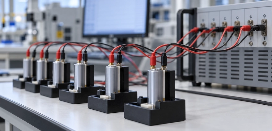
Lithium Battery Discharge Curves: Cell Consistency, Resistance, and Quality
Commercial Summary: Himax Electronics presents this technical guide to support evidence-based battery evaluation. It outlines how discharge data can inform cell screening and custom pack design, while clarifying why test conditions and supporting measurements are essential to quality assessment.

Key Takeaways

  • A lithium battery discharge curve plots voltage against discharge time or delivered capacity. It can reveal voltage sag under load, the discharge plateau, usable capacity, and behavior near the end of discharge.
  • Before comparing cell consistency, align the chemistry, charging procedure, initial state of charge, temperature, discharge current, and cutoff conditions.
  • The voltage drop when a load is applied relates to resistance and polarization, but voltage differences across an entire curve cannot be converted directly into a fixed internal resistance.
  • Variation among multiple cells’ discharge curves can provide clues about capacity consistency, impedance differences, and batch stability.
  • Discharge curves support manufacturing quality assessment, but they cannot independently establish safety, long-term life, or a specific manufacturing defect.
  • Custom battery pack selection should consider curves under representative loads, temperature rise, pulse testing, and batch data rather than rated capacity alone.
Two lithium cells with the same rated capacity may deliver different runtimes or trigger low-voltage warnings at different points once installed in equipment. Some show little difference under light loads but develop greater voltage sag as the load increases. Others start at similar voltages but enter the end-of-discharge region earlier.
Lithium battery discharge curves often provide clues to these differences. For equipment manufacturers, purchasing teams, and battery developers, understanding the curves can help assess runtime, cell consistency, internal resistance, and manufacturing process stability. The key is to compare data under controlled conditions and distinguish a possible explanation from a verified cause.

How to Read a Lithium Battery Discharge Curve: Start with the Axes and Test Conditions

A typical lithium battery discharge curve shows voltage on the vertical axis and discharge time or delivered capacity on the horizontal axis. Each horizontal-axis format answers different questions.
Curve Format Primary Use Interpretation Considerations
Voltage vs. time Evaluate runtime and voltage behavior under a specified load Runtime cannot be compared directly when discharge currents differ
Voltage vs. capacity Compare plateau shape, delivered capacity, and the end-of-discharge region Charging procedure, current, temperature, and cutoff voltage must be consistent
Voltage vs. normalized capacity Compare curve shapes across cells Normalizing each cell to its own capacity can conceal actual capacity differences
Pulse voltage response Analyze voltage sag during loading and recovery after unloading Sampling time, pulse duration, and initial conditions must be defined
Also distinguish terminal voltage under load from open-circuit voltage. Voltage measured while equipment is operating is affected by current, resistance, and polarization. It is not the same as open-circuit voltage measured after sufficient rest.
Curve shape also varies by chemistry. Lithium iron phosphate cells typically have a relatively flat plateau, while some nickel-manganese-cobalt cells show a more pronounced voltage change as discharge progresses. A flatter curve does not, by itself, indicate better manufacturing quality.

How Do Discharge Curves Reflect Cell Consistency?

Cell consistency describes how closely cells match in capacity, impedance, self-discharge, state of charge, and other characteristics. Overlaying discharge curves from a single test reveals only part of that picture.

Similar Starting Voltages Do Not Establish Overall Consistency

Two cells can begin at similar voltages while differing in actual capacity, resistance, or aging. In chemistries with a relatively flat voltage plateau, a small voltage difference does not necessarily indicate the same state of charge.
Cell matching should therefore include capacity, resistance measured under specified conditions, and self-discharge data rather than resting voltage alone.

Evaluate Plateau Voltage and End-of-Discharge Position Together

Under identical test conditions, a cell with a lower voltage plateau may have greater polarization, a lower initial state of charge, or a different temperature. If it also reaches the cutoff voltage earlier, it delivers less capacity under that test condition. Further testing is needed to distinguish a capacity limitation from early cutoff caused by voltage sag.
Curve Behavior Possible Explanations Follow-Up Checks
Different starting voltages Differences in initial state of charge, rest time, or self-discharge Standardize charging and rest procedures; review storage records
Different voltage drops when load is applied Differences in cell impedance, contact resistance, or temperature Pulse testing, fixture inspection, and temperature measurement
Persistent deviation in the middle plateau Differences in polarization, state of charge, or electrochemical characteristics Low-rate retesting and impedance analysis
Earlier entry into the end-of-discharge region Less usable capacity or earlier arrival at the cutoff condition Low-rate capacity testing and initial-condition checks
Irregular voltage jumps Poor contact, test equipment range switching, or protection activation Raw current data, wiring inspection, and equipment logs
A study published in Scientific Reports analyzed a large population of new cells and examined how cell-to-cell variation changed with discharge rate. Its findings show that consistency depends on the test rate: similar performance under a light load does not replace validation under higher loads. Reference: Rate dependence of cell-to-cell variations of lithium-ion cells

Total Pack Voltage Can Hide Individual Cell Differences

In a series-connected pack, one cell may reach its low-voltage protection threshold while the others still have charge remaining. This can limit the pack’s usable capacity.
Record individual cell voltages, current, and temperature alongside the pack discharge curve. Total voltage alone may not identify the cell that triggers an early shutdown.

What Is the Relationship Between Discharge Curves and Internal Resistance?

Resistance and Polarization Affect Voltage Under Load

The following simplified relationship helps explain discharge behavior:
Terminal voltage under load ≈ Open-circuit voltage at the current state − Ohmic voltage drop − Voltage loss due to polarization
The ohmic drop depends on current. Polarization includes electrochemical and transport processes operating over different timescales. Internal resistance should therefore not be treated as a single value that remains unchanged across temperature, state of charge, and load.
The same cell may produce different DC resistance results at low temperature, at a lower state of charge, or with a different pulse duration.

Estimating Resistance from Voltage Changes Requires a Defined Method

A typical pulse test changes the current under specified conditions and measures the voltage response at a defined time:
Effective DC resistance at the specified timescale ≈ Voltage decrease ÷ Current increase
For example, if a 5A increase in current produces a 0.10V drop at the specified sampling time, the corresponding effective resistance is approximately 20mΩ. That result applies to the test conditions used. Contact and measurement errors must be controlled, and the result should not be treated as the cell’s fixed resistance under every operating condition.
Test Factor Why It Affects the Result Comparison Requirement
State of charge Reaction and transport characteristics vary across the charge range Use the same state of charge
Temperature Affects ion transport and reaction kinetics Align ambient and cell temperatures
Sampling time Different measurement times include different polarization contributions Specify the measurement time after the current change
Pulse current and duration Affect voltage response, heating, and cell state Use the same test procedure
Wiring and contact conditions Fixtures and cables can introduce additional voltage drop Use appropriate four-wire measurement and verify contact quality
Measurement method AC impedance and DC pulse tests characterize different responses Do not directly equate results from different methods
Dividing the voltage difference between two cells at the same discharge time by the current does not establish their resistance difference. Their states of charge and open-circuit voltages may already differ.
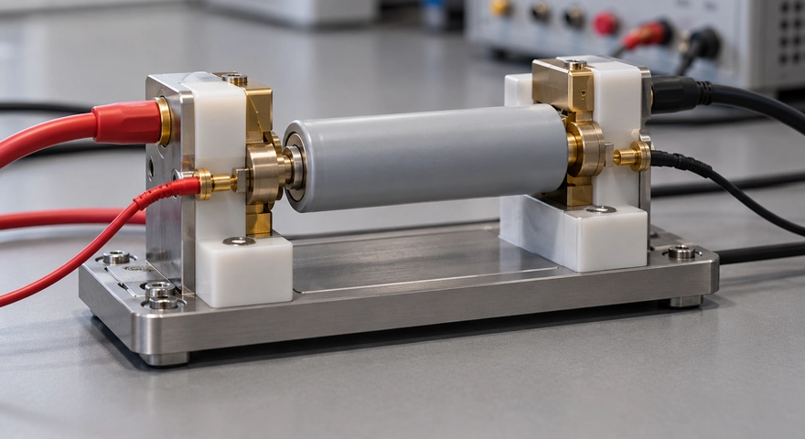
How Do Discharge Curves Relate to Manufacturing Quality?

A discharge curve is one electrochemical expression of the manufacturing outcome. Material and process variation can affect capacity, polarization, and curve shape, but these relationships are generally not one-to-one.
Manufacturing Stage Characteristics It May Affect Potential Clues in Discharge Data
Slurry mixing and coating Active material distribution, coating loading, and conductive networks Variation in capacity, plateau voltage, or rate performance
Calendering and pore structure control Electrode contact and electrolyte transport Differences in polarization under heavier loads
Electrolyte filling and wetting Electrolyte distribution and electrode wetting Higher impedance, unstable output, or abnormal rate performance
Tab and interconnect welding Current paths and connection resistance Greater voltage sag under load or abnormal localized heating
Formation and aging Interface development and screening for abnormal cells Shifts in capacity, impedance, or curves after storage
Environmental and contamination control Side reactions, self-discharge, and long-term stability Some issues may emerge after storage or cycling
These observations suggest investigation paths rather than confirmed diagnoses. Excessive voltage sag, for example, may result from internal connections, low temperature, aging, or poor external fixture contact. A discharge curve alone cannot establish a welding defect.
Manufacturing quality assessment should also include batch statistics and process traceability. For the same model under the same test conditions, stable distributions of capacity, energy, voltage at specified capacity points, and pulse resistance are more informative than a single smooth curve.
Even closely overlapping curves cannot rule out latent internal defects or establish compliance with all applicable safety requirements.

How Do You Build a Meaningful Discharge Test?

Standardize the Test Conditions

Define the model, chemistry, cycling history, charging procedure, rest time, temperature, and cutoff conditions before testing. New and previously used cells should not be pooled to evaluate manufacturing consistency.
For cells with the same rated model, also specify whether testing uses the same absolute current or a C-rate calculated from a common capacity reference. This avoids introducing differences through inconsistent test currents.

Evaluate Capacity, Energy, and Representative Loads

Similar delivered capacity does not mean identical delivered energy. A cell operating at a lower voltage throughout discharge may deliver less energy even if its amp-hour output is similar.
For motor-driven equipment, communications modules, medical devices, and other applications, select pulse, constant-power, or dynamic-load tests that reflect actual use. Passing a low-rate laboratory capacity test does not establish that voltage sag and runtime will meet the equipment’s requirements.

Retain Raw Data and Analyze Batches

Record voltage, current, temperature, and time together. Depending on the application, evaluate capacity spread, energy spread, voltage differences within defined regions, and resistance distributions.
Incremental capacity analysis and differential voltage analysis can extract features that are difficult to identify in the original curves. However, these methods are sensitive to sampling accuracy, test rate, temperature, and data processing, so their interpretation requires defined limits.
Research on battery manufacturing process control has proposed using near-equilibrium voltage curves and differential voltage analysis to derive metrics related to electrode capacity and formation. These techniques can supplement routine capacity testing but require suitable models and validation. Reference: Differential voltage analysis for battery manufacturing process control

What Should You Ask a Custom Battery Pack Supplier?

Information to Confirm Why It Matters
Whether the curve represents an individual cell or a complete pack Separates cell behavior from the effects of interconnects, protection electronics, and other pack components
Discharge mode and load level Shows whether the test represents actual equipment operation
Charging procedure, temperature, and cutoff conditions Establishes whether the data are comparable
Sample size and batch coverage Avoids basing decisions on a single sample
Individual cell voltages, temperature rise, and protection records Helps identify the factors limiting pack performance
Initial performance and results after cycling or storage Shows how consistency changes with use and time
For custom projects, acceptance criteria should reflect equipment requirements. Low-voltage warning thresholds, load pulse duration, and operating temperature range can all affect compatibility. A single voltage-spread or resistance-spread limit should not be applied indiscriminately across different projects.

Lithium Battery Discharge Curve FAQ

Does a Flatter Discharge Curve Mean Better Battery Quality?

No. Curve shape depends primarily on chemistry and is also affected by discharge rate, temperature, and test conditions. Compare similar products under equivalent conditions, using capacity, energy, impedance, temperature rise, and batch stability as supporting evidence.

Why Do Two Cells with the Same Capacity Have Different Discharge Curves?

Capacity is only one metric. Resistance, polarization, initial state of charge, temperature, and aging can change the curve. Even cells with similar amp-hour output may differ in voltage under load and delivered energy.

Can Internal Resistance Be Calculated Directly from a Standard Constant-Current Discharge Curve?

A standard curve generally does not provide a clearly defined resistance value by itself. Open-circuit voltage and polarization change during discharge. Compare DC resistance using a method that specifies state of charge, temperature, pulse current, and sampling time.

Do Similar Voltages Mean Similar States of Charge in Lithium Iron Phosphate Cells?

Not necessarily. Lithium iron phosphate cells have a relatively flat middle plateau. The voltage-to-charge relationship is also affected by temperature, rest conditions, and hysteresis. A small voltage difference alone does not establish matching states of charge.

Does an Earlier End-of-Discharge Drop Indicate a Manufacturing Defect?

Not necessarily. Possible causes include capacity differences, insufficient initial charge, low temperature, higher discharge current, or cutoff conditions. First account for test conditions and usage history, then evaluate the product specifications and retest results.

Can BMS Balancing Resolve Every Cell Consistency Issue?

No. Balancing primarily adjusts differences in stored charge. It cannot restore lost capacity or eliminate high resistance or manufacturing defects. Cell matching and quality control remain important.

Can One Discharge Test Establish Battery Life?

No. A single test characterizes output at that time and under those conditions. Life assessment also requires cycling, storage, and relevant environmental testing, with clearly defined performance endpoints.

About Himax Electronics

Himax Electronics focuses on custom battery and power solutions for complex applications worldwide. The company also offers proprietary lithium-ion battery packs, power supplies, chargers, and accessories to meet industry-specific requirements. Each project calls for an assessment of load profiles, operating temperatures, available space, and charging conditions. Contact Himax Electronics to discuss cell configurations, protection strategies, and testing requirements that support compatibility between the battery and your equipment.

2027 Home Backup Power Guide
Commercial Summary: Himax Electronics presents this guide to clarify the engineering considerations behind residential battery backup. It examines cell chemistry, system integration, and operating limits to help readers evaluate power solutions using verifiable specifications.

Key Takeaways

  • LiFePO4 batteries store energy, but home backup power also requires an inverter, a battery management system, and compatible electrical connections.
  • Size energy capacity and power output separately: capacity helps determine runtime, while output power determines which devices can operate together.
  • Refrigerators, pumps, and other motor-driven appliances have startup demands that may exceed their normal running power.
  • Portable power stations, installed home battery systems, and uninterruptible power supplies differ in how they connect and respond to an outage.
  • Cell quality, manufacturing consistency, protection features, operating temperatures, and maintenance all affect real-world performance.
During a power outage, households often need to keep lights, communications, food refrigeration, and essential equipment running rather than power every appliance at once. Planning around those priorities is more useful than choosing a battery based only on a larger capacity number.
As you prepare your home backup power plan for 2027, lithium iron phosphate batteries are one storage technology worth understanding. How do they provide backup electricity? How much capacity do you need? Can they take over automatically when the grid goes down? This guide approaches those questions from a battery manufacturing and system design perspective, with calculations you can use to plan household power needs.

How Do LiFePO4 Batteries Provide Home Backup Power?

Lithium iron phosphate batteries, commonly called LFP or LiFePO4 batteries, are a type of lithium-ion battery. They store energy through a compatible charging system when power is available, then release that energy to connected equipment during an outage.
Batteries supply direct current, or DC, while many household appliances require alternating current, or AC. A home battery backup system therefore typically includes the following stages:
Utility Power or Compatible Solar Charging Equipment → Battery Storage → Battery Management and Protection → Inverter or Regulated Output → Connected Devices
The battery management system, or BMS, monitors conditions such as cell voltage, temperature, and current, and activates protection functions according to its design. The inverter converts DC electricity into the AC electricity appliances require.
Systems connected to permanent household circuits also need appropriate isolation, transfer equipment, and electrical distribution design.
System Component Main Function What to Check
LiFePO4 battery pack Stores and releases energy Rated energy, permitted charging and discharging current, and operating temperatures
Battery management system Monitors conditions, balances cells, and provides protection Protection thresholds, temperature monitoring, and communication compatibility
Inverter Converts DC power into AC power Continuous output, startup-load capability, output voltage, and frequency
Charging equipment Replenishes energy from utility power or another source Charging profile, voltage range, current, and temperature limits
Transfer and distribution equipment Manages power sources and backup circuits Grid isolation, transfer method, grounding, and circuit protection
Cables, connectors, and protective devices Carry current and provide fault protection Current ratings, connection reliability, and short-circuit protection
Using LiFePO4 cells is one element of a backup system. That specification alone does not establish the performance of the finished product.
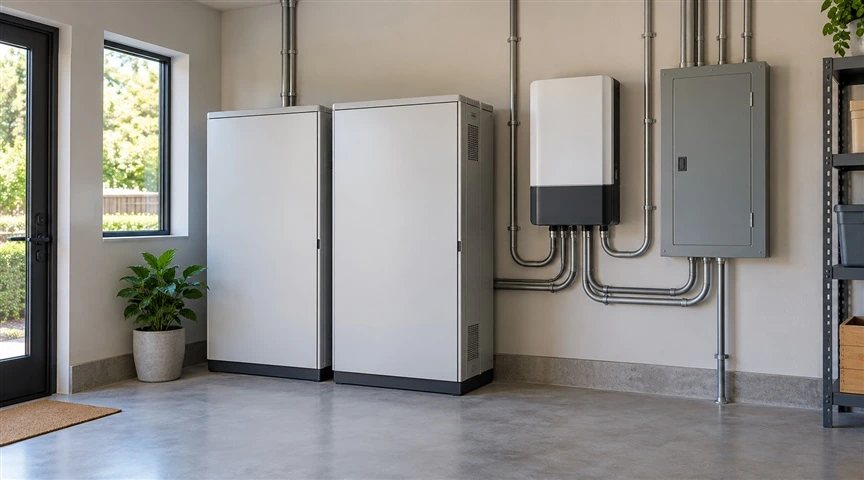
LiFePO4 Home Backup System Components

Why Use LiFePO4 Batteries for Home Emergency Power?

LiFePO4 chemistry offers favorable thermal stability and cycle-life potential for energy storage applications. However, those characteristics depend on suitable cell design, manufacturing quality, and operating conditions.
For homeowners, the practical considerations include the following:
Consideration LiFePO4 Application Characteristics Conditions That Also Matter
Repeated cycling Suitable for storage applications involving repeated charging and discharging Depth of discharge, temperature, charge and discharge rates, and test conditions
Thermal stability Cathode material characteristics support system safety design Overcharging, short circuits, mechanical damage, and thermal runaway still require protection
Home installation Can be assembled into battery modules with different capacities Available space, weight, cooling, and environmental conditions
Standby use Stores energy before an outage occurs Calendar aging, standby consumption, and maintenance strategy
Energy density May require more space or weight than some other battery chemistries Evaluate the dimensions and weight of the complete product
From a manufacturing perspective, chemistry is only part of the evaluation. Cell capacity and internal resistance consistency, weld quality, electrical insulation, temperature sensor placement, and fault protection all affect finished battery pack performance.
Sandia National Laboratories combines testing expertise with research into thermal reactions to evaluate the safety and reliability of electrochemical energy storage. This supports evaluating residential storage at the cell, module, and complete-system levels. Reference: Sandia National Laboratories—Energy Storage Safety and Reliability

How Much Home Backup Battery Capacity Do You Need?

Start with two questions:
Which devices need to keep running, and for how long?
Lighting, internet equipment, and refrigeration have different energy requirements from air conditioning, electric water heating, and electric cooking. Separating essential loads from appliances you can temporarily leave off makes capacity planning more manageable.

Estimate Energy Needs From Actual Consumption

Use this basic calculation:
Energy Use (Wh) = Average Power (W) × Operating Time (h)
The following figures are examples, not measured consumption for every household or device.
Device Example Average Power or Energy Requirement Planned Use Estimated Energy Use
LED lighting 20W combined 5 hours 100Wh
Modem or fiber terminal and router 15W combined 8 hours 120Wh
Refrigerator Measured average power of 40W 8 hours 320Wh
Laptop Average input power of 50W 3 hours 150Wh
Phone charging Approximately 40Wh delivered in total Per charging session 40Wh
Total — — 730Wh
Refrigerators cycle on and off. Their energy use changes with room temperature, temperature settings, door openings, and the condition of stored food. Multiplying nameplate running power by the entire outage duration may not provide a useful estimate.

Account for Losses and Backup Reserves

A simplified sizing calculation is:
Required Rated Battery Energy ≈ Load Energy Demand ÷ (Planned Usable Discharge Fraction × Overall Conversion Efficiency)
Using the 730Wh example, assume a planned usable discharge fraction of 90% and overall conversion efficiency of 85%:
730 ÷ (0.90 × 0.85) ≈ 954Wh
These percentages illustrate the calculation; they are not specifications for a particular product. Also account for inverter standby consumption, low temperatures, battery aging, and the reserve needed if an outage lasts longer than expected.
If a manufacturer provides measured usable AC output energy under relevant test conditions, that figure can be a more direct starting point. Avoid deducting the same losses twice.

Why Can a Battery Have Enough Capacity but Still Fail to Run an Appliance?

Energy capacity and output power answer different questions:
  • Wh or kWh: How much energy is stored, which helps estimate runtime.
  • W or kW: How much power can be supplied, which helps determine whether equipment can operate.
For example, a power station rated at 2kWh with a continuous output limit of 1,000W should not be assumed capable of continuously running a 2,000W appliance.
Refrigerators, pumps, and other motor-driven equipment may briefly demand more power when starting. Compatibility depends on the duration of that demand, the inverter’s overload capability over time, and the current limits of the battery and BMS. A peak-power number alone is not enough.
Load Type Main Power Considerations Planning Approach
Routers and lighting Extended operation at low power and standby losses Check low-load efficiency and measured runtime
Refrigerators and compressor equipment Startup demand and intermittent operation Verify startup capability and estimate energy use from measurements
Pumps and other motor loads Starting current, power factor, and operating duration Confirm compatibility with the equipment and power-system suppliers
Electric kettles and space heaters High continuous demand and rapid energy consumption Limit operating time or plan an alternative
Equipment sensitive to power interruptions Transfer time and power quality Configure and verify a solution that meets the equipment’s requirements
For equipment that supports health or life-sustaining functions, establish a backup plan and failure-response procedure based on the equipment manufacturer’s requirements. Ordinary emergency power capacity alone does not establish suitability.

Portable Power Stations, Home Battery Systems, and UPS Units: What Is the Difference?

These products may all use LiFePO4 batteries, but their connection methods and operating purposes differ.
Solution Typical Connection What to Verify During an Outage
Portable power station Devices plug directly into its output ports Whether manual action is needed and whether an appropriate standby mode is supported
Installed home battery system Professionally connected to selected circuits or the home’s electrical distribution system Islanded operation, grid isolation, and automatic transfer capability
Uninterruptible power supply, or UPS Supplies specified equipment with short-term backup or continuity support Architecture, transfer time, waveform, load compatibility, and runtime
Products labeled “EPS,” “backup power,” or “UPS function” may have different transfer times and supported loads. Whether a computer, networking device, or controller stays on depends on its tolerance for a power interruption and the system’s verified behavior.
A portable power station can supply compatible devices directly according to its instructions. Connecting backup power to permanent household circuits requires an appropriately qualified installer and suitable isolation and transfer equipment.

Do not feed power into household wiring through a wall outlet.

Can Solar Panels Keep Your Home Powered Through an Extended Outage?

Solar panels can replenish a battery, but energy production depends on sunlight, weather, shading, panel orientation, and system efficiency. A panel’s rated wattage is not continuous all-day output.
The U.S. Department of Energy explains that conventional residential solar systems generally shut down when utility power fails. Supplying loads during an outage requires appropriately configured inverter and storage equipment. Reference: U.S. Department of Energy—Solar and Resilience Basics
When planning solar charging with LiFePO4 home battery storage, check:
  • Solar input voltage, current, and charge-controller limits.
  • Whether solar charging remains available while the grid is down.
  • Whether the system can restart as designed after a low-battery shutdown.
  • Whether expected energy production can meet demand during consecutive cloudy or rainy days.
If daily charging supplies less energy than the household consumes, the battery’s charge level will continue to fall. Planning for an extended outage should include load reduction and other practical charging options.
Solar Charging for Home Battery Backup

What Should You Check From a Battery Manufacturing Perspective?

Compare specific models using documented specifications rather than broad descriptions such as “long life” or “large capacity.”
Item to Review Information to Request
Cell and battery pack specifications Chemistry, rated voltage, rated energy, and production traceability
Service-life data Test temperature, charge and discharge rates, depth of discharge, and capacity-retention endpoint
Output performance Continuous power, permitted overload duration, and shared port limits
Temperature management Charging and discharging temperature ranges, low-temperature protection, and heating conditions
Protection features Overcharge, overdischarge, overcurrent, short-circuit, and temperature protection
Testing and certification documents Applicable product category, exact model, report scope, and requirements for the intended market
Expansion compatibility Approved module combinations, communication protocols, and configuration limits
Service and maintenance Warranty terms, troubleshooting support, replacement parts, and end-of-life recycling options
Cycle count should not be converted directly into years of service. Even a backup battery that cycles infrequently experiences calendar aging. Temperature and the charge level maintained over time influence that process.

Routine Maintenance: Keep Emergency Power Ready

Standby operation requires a balance between available outage energy and battery care. Storage recommendations for another product should not automatically be applied to a home battery system that stays connected and ready for use.
Usage Scenario Maintenance Guidance
Continuously connected standby operation Use the manufacturer’s backup mode and check system status and alerts as instructed
Portable power station stored for an extended period Follow the specified storage charge level and inspection schedule; avoid prolonged storage at very low charge
Cold conditions Check charging temperature limits and do not bypass protection or improvise battery heating
Damp, flood-prone, or hot conditions Reassess the installation location; stop operating equipment affected by water or abnormal conditions and contact a professional
Periodic functional checks Verify essential-load operation, transfer behavior, and alerts under controlled conditions
LiFePO4 batteries have a relatively flat voltage profile across much of their operating range. A single voltage reading may not accurately show the remaining charge.
Use the BMS estimate together with the manufacturer’s prescribed calibration procedure. Do not repeatedly force deep discharges simply to “calibrate” the battery.

LiFePO4 Home Emergency Power FAQ

How long can a 1kWh LiFePO4 power station run a refrigerator?

You cannot reliably determine runtime by dividing 1kWh by the refrigerator’s nameplate power alone. You need the power station’s usable output energy and the refrigerator’s average consumption under the expected conditions.
For example, 800Wh of usable energy divided by an average load of 40W gives a simplified estimate of 20 hours. Actual runtime also depends on startup behavior, standby losses, and operating conditions.

Can LiFePO4 batteries be used indoors?

Check whether the complete product is approved for indoor use and whether the location meets its cooling, environmental, and protection requirements.
Battery chemistry alone does not establish that a pack is suitable for a bedroom, enclosed cabinet, or exit route.

Should a home emergency battery always stay fully charged?

That depends on the product’s standby strategy. A permanently connected home battery system and a portable power station placed in storage serve different purposes.
Follow the manufacturer’s backup reserve or storage charge settings rather than applying one charge percentage to every product.

Can a backup battery keep equipment running without interruption?

That depends on system architecture, transfer equipment, and the connected device’s tolerance for an interruption.
Automatic transfer does not guarantee that every device will stay on without restarting. For sensitive equipment, check the specified performance and verify compatibility.

Are LiFePO4 batteries unable to catch fire?

No. Favorable material thermal stability does not eliminate system-level risk.
Overcharging, short circuits, manufacturing defects, water intrusion, and mechanical damage can still cause failures. Manufacturing controls, protective design, and proper use all help reduce risk.

Can I connect batteries from different brands or with different capacities in parallel?

Do not connect them without an approved compatibility assessment. Voltage, state of charge, BMS behavior, communication protocols, wiring, and protection must all be considered.
An unverified combination may produce high equalization currents or uneven current sharing. Use an expansion configuration explicitly supported by the system supplier.

About Himax Electronics

Himax Electronics focuses on custom battery and power solutions for complex applications worldwide. The company also provides proprietary lithium-ion battery packs, power supplies, chargers, and accessories to meet specific industry requirements.
For home emergency power and related equipment development projects, share your target backup duration, continuous and startup loads, installation space, operating temperatures, and charging requirements with Himax Electronics to discuss battery and supporting power solutions for your application.
Commercial Summary: This editorial guide from Himax Electronics examines fall travel power needs through battery engineering principles. It distinguishes battery types, explains operating limits, and outlines maintenance practices to support informed equipment selection and use.

Key Takeaways

  • Understand the differences between starter batteries, EV traction batteries, and portable power station batteries, and maintain each according to its intended use.
  • Check battery health, terminals, and charging systems before leaving. A charge indicator alone does not tell you the battery’s overall condition.
  • Plan power use around the actual energy needs of your portable refrigerator, lighting, and electronics, with a reserve for changes in your itinerary.
  • Account for overnight temperature drops, cold-weather charging, condensation, and heat buildup inside a parked vehicle.
  • Use compatible chargers, cables, and protective devices, then inspect and store your batteries properly after the trip.

Introduction

Fall is a great time for a road trip, but chilly mornings, mountain temperature swings, and overnight camping can put added demands on your power setup. Slow engine cranking, a portable refrigerator shutting off overnight, or intermittent phone charging may point to battery aging, insufficient capacity, loose connections, or incompatible charging conditions.
From a battery manufacturing and system design perspective, effective fall road trip battery care involves more than keeping batteries charged. Cell performance, the battery management system, charging controls, and connected loads all affect the result. This guide covers what to check before departure, how to manage power on the road, and what to do when you get home.

Know Which Battery Powers What

Batteries labeled “12V” are not necessarily interchangeable. Likewise, maintenance practices for a vehicle’s starter battery should not automatically be applied to a portable power station. Battery designs differ in their intended loads, charging requirements, and discharge capabilities.
Battery or Power System Typical Uses Fall Travel Considerations Maintenance Focus
Low-voltage starter or auxiliary battery Engine starting in gas-powered vehicles, low-voltage accessories, and vehicle controls; some EVs also have a low-voltage auxiliary battery Output in cooler weather, parked-vehicle power draw, and aging Check battery health and avoid prolonged undercharging
EV traction battery Vehicle propulsion and, on supported models, power for external equipment Temperature, route energy demand, charging access, and external power settings Use the vehicle’s built-in charging and thermal management functions
Portable power station or separate house battery Portable refrigerators, lights, laptops, and camping equipment Usable energy, continuous output, and charging temperature Match the system to the loads and use compatible charging methods
Batteries inside phones, cameras, and other devices Communication, navigation, and photography Cold-weather runtime changes, charging protocols, and moisture at connectors Use compatible accessories and avoid excessive heat or charging through damp ports
Starter batteries are designed primarily to deliver high current for short periods. They generally are not intended for repeated deep discharges from camping equipment. For extended use while parked, consider a separate power source that preserves the energy needed to start or wake up the vehicle.

Before You Leave: Look Beyond the Charge Indicator

Inspect the Battery and Connections

Check for a swollen or cracked case, leakage, loose mounting hardware, and visible terminal corrosion. For portable power stations, also inspect outlets, charging ports, and cables for damage, scorching, or loose connections.
Stop using a battery that shows swelling, an unusual odor, or persistent abnormal heating, and contact a qualified service provider. Do not open a battery pack yourself or remove the covers from a vehicle battery labeled maintenance-free.

Check Both Charge Level and Battery Health

State of charge, or SOC, describes how much charge is currently available. State of health, or SOH, reflects aging-related changes in characteristics such as capacity and output capability. A battery may show a full charge yet struggle to start an engine because its internal resistance has increased.
If your vehicle has been cranking slowly, repeatedly losing charge, or has an uncertain battery history, arrange a pre-trip inspection. A technician can assess starting performance, the charging system, and abnormal key-off current draw using procedures appropriate for the battery type.
A single resting-voltage measurement does not provide a complete picture of battery health.

Consider the Effects of Frequent Short Drives

Frequent starts, short commutes, and parking-mode recording can affect the balance between energy used and energy replaced. AAA’s automotive guidance identifies short trips that do not adequately recharge the battery as a contributing concern. Its battery replacement guidance also emphasizes matching the battery to the vehicle’s required type, dimensions, and electrical specifications. Reference: AAA Automotive Battery Guidance
A short drive should not be treated as confirmation that a depleted battery has been fully recharged. If external charging is needed, use a charger compatible with the battery type and follow the vehicle manual’s connection points and procedures.

How Fall Temperature Swings Affect Batteries

As temperatures drop, electrochemical reactions and ion transport can slow down. Depending on the battery, this may increase internal resistance, reduce voltage under load, and decrease available energy. These effects can become more noticeable in an aging battery during a morning start or a high-power load.
Discharging a battery in cold weather and charging it in cold weather are different operating conditions. A battery that can supply power at a given temperature may not be approved for charging at that same temperature.
Research involving Argonne National Laboratory examines the relationship between low temperatures, higher charging rates, and lithium plating on graphite anodes. The practical implication is that lithium-ion charging controls need to account for both temperature and current. A battery accepting current does not, by itself, establish that the charging conditions are appropriate. Reference: Research on Graphite Electrode Charging in Lithium-Ion Batteries
Common Fall Travel Scenario Possible Effects Recommended Response
Cold mornings in mountainous or high-elevation areas Reduced output, available energy, or charging speed Check the product’s operating limits and allow additional energy reserves
Charging a portable power station in cold conditions Low-temperature protection may limit or stop charging Follow the manual and let the battery reach its permitted charging temperature
Leaving a power station in a closed vehicle on a sunny day Heat buildup may affect cooling and battery life Keep it out of direct sunlight and maintain ventilation clearance
Rain, fog, or moving cold equipment into warm, humid air Damp connectors or condensation Confirm that the equipment and connectors are dry before connecting power
Extended camping while parked Ongoing energy use may trigger low-voltage protection Reduce nonessential loads and plan separate power and recharging options
Charging and discharging temperature limits, recovery conditions, and protection behavior vary by model. Follow the applicable manual. Do not heat a battery with an open flame, heat gun, or another unapproved method, and do not bypass low-temperature protection.
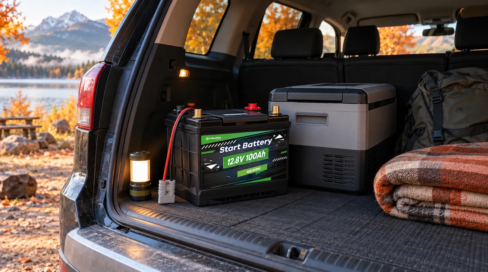
hiamx Car Starter Battery

Plan Power for Your Devices: Calculate Energy, Then Check Output

Comparing capacity numbers alone can overlook important operating requirements. Energy capacity helps estimate runtime. Continuous output, startup demand, and port limits determine whether a power source can run a device.

Estimate Daily Energy Use in Watt-Hours

Use this basic calculation:
Energy Use (Wh) = Average Power (W) × Operating Time (h)
The following example illustrates the calculation. It does not represent the actual consumption of every device in these categories.
Device Example Assumption Usage Estimated Energy Use
Portable refrigerator Measured average power of approximately 20W 10 hours Approximately 200Wh
LED lighting 8W 4 hours Approximately 32Wh
Laptop Average input power of 45W 2 hours Approximately 90Wh
Phone and camera charging Approximately 40Wh delivered in total Daily total Approximately 40Wh
Total — — Approximately 362Wh
A compressor refrigerator typically cycles on and off. Its energy use depends on ambient temperature, the temperature setting, the initial temperature of its contents, and how often it is opened. Its nameplate power should not automatically be used as its all-day average.
For example, suppose a power station has a rated energy capacity of 500Wh. If you assume an overall usable-energy factor of 85% under a particular set of conditions, it would deliver approximately 425Wh to connected loads.
That percentage is an illustration, not a product specification. Actual usable energy depends on conversion losses, standby consumption, temperature, aging, and protection settings. With an estimated daily demand of 362Wh, you should still consider a longer stay or uncertain access to charging the next day.

Check Ports and Startup Requirements

Devices such as compressor refrigerators may briefly draw more current when starting. A power station can shut down because of insufficient output capability even when it still has energy remaining.
Before buying or connecting equipment, check:
  • Output voltage, polarity, and connector compatibility.
  • Individual-port limits and shared limits when multiple ports are used.
  • Device startup requirements and the power source’s permitted surge output.
  • Cable current rating, length, and connection quality.
  • Supported charging protocols and power profiles for interfaces such as USB-C.
Using DC power may reduce some conversion steps, provided the voltage range, regulation, and connectors are compatible. A plug fitting into a socket does not establish electrical compatibility.

On the Road: Reduce Battery Drain and Power Interruptions

Identify What Stays Powered After Parking

Depending on the vehicle, accessory sockets, USB ports, and cargo-area outlets may turn off with the ignition or remain active. Check the owner’s manual and confirm how your dash cam’s parking mode, refrigerator, and other connected equipment operate.
A low-voltage disconnect can help limit discharge, but its cutoff setting may not suit every vehicle, battery condition, or ambient temperature. It should not be treated as a guarantee that the vehicle will start.

Do Not Rely on a Fixed Idling Time to Recharge

Charging at idle depends on alternator controls, vehicle electrical loads, and battery condition. There is no single idling duration that reliably indicates how much energy has been restored.
Never run an engine in an enclosed or poorly ventilated space, and do not rely on overnight idling to power camping equipment.

Secure Equipment and Manage Moisture and Heat

Secure battery packs and portable power stations so they cannot slide or become impact hazards during sudden braking. Keep cables clear of door pinch points and prevent metal objects from contacting exposed terminals.
Leave ventilation openings unobstructed. Do not cover operating power equipment with clothing or sleeping bags.
If your EV supports external power output, use approved accessories, check the output limits, and set an appropriate discharge cutoff to preserve energy for the next leg of your trip.

After the Trip: Maintain and Store Each Battery Correctly

Post-trip care affects how your equipment performs the next time you use it. Inspect for moisture, cable wear, unusual heating, and noticeable changes in runtime.
Battery Type or Condition Post-Trip Maintenance
Undercharged lead-acid starter battery Recharge promptly using a compatible method and avoid leaving it depleted
Lithium-ion portable power station going into extended storage Follow the manual’s storage charge guidance, check periodically, and avoid prolonged storage at very low charge
Equipment exposed to rain, fog, or condensation Confirm it is dry and free of abnormalities before use; seek professional service if internal water intrusion is suspected
Repeated protective shutdowns or noticeably reduced capacity Record temperature, connected loads, and fault behavior, then contact support for diagnosis
Storage charge levels and inspection intervals vary with cell chemistry and battery management design. Avoid assuming that every battery should be stored fully charged or recharged on the same schedule.

Fall Road Trip Battery Care FAQ

Does slow engine cranking in fall mean the battery needs replacement?

Not necessarily. Low charge, battery aging, poor terminal connections, charging-system problems, and starter-system faults can all contribute. Use diagnostic results to guide the decision rather than replacing the battery based on a single slow start.

Can lithium iron phosphate batteries charge in cold weather?

Check the specific product’s charging temperature range, low-temperature protection, and heating design. Lithium iron phosphate, or LiFePO4, is a lithium-ion chemistry; its name alone does not establish its cold-weather charging capability.
Products with self-heating features still require the correct preheating and charging sequence.

Can I run a portable refrigerator from my vehicle’s starter battery overnight?

That depends on refrigerator consumption, parking duration, battery health, and ambient temperature, among other factors. Extended use may consume the reserve needed for starting.
For repeated overnight operation, evaluate a separate house battery or portable power station and calculate the refrigerator’s actual energy use.

Why does a device shut off when the power station still shows charge remaining?

Possible causes include excessive continuous power demand, high startup current, cold-related voltage sag, cable voltage drop, loose connections, or a battery management system protection event.
Turn off the load and check the fault indication. Address the cause before restoring operation according to the manual.

What is the difference between Ah and Wh when choosing a portable power station?

Amp-hours, or Ah, measure charge capacity. Watt-hours, or Wh, measure energy. Wh is more useful for estimating runtime when comparing products with different battery voltages.
A rough calculation using rated values is:
Wh = Nominal Voltage × Ah
Still, distinguish between the battery’s rated energy and the energy actually available at the output.

Can a standard lithium battery pack replace a vehicle’s starter battery?

Matching nominal voltage is not enough. Starting current, charging-system compatibility, battery management behavior, operating temperatures, mounting requirements, and vehicle specifications also matter.
Some vehicles require battery registration or system adaptation after replacement. Have the work performed by someone qualified for the vehicle and battery system.

About Himax Electronics

Himax Electronics focuses on custom battery and power solutions for complex applications worldwide. The company also provides proprietary lithium-ion battery packs, power supplies, chargers, and accessories to address specific industry requirements.
For vehicle accessories, outdoor equipment, and other professional applications, share your operating temperatures, supply voltage, continuous and peak loads, target runtime, and available installation space with Himax Electronics to discuss a battery and power solution suited to your operating conditions.


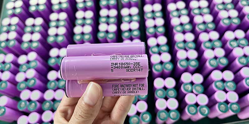
Samsung INR18650-35E 3400mAh 18650 cell for GPS locator battery - top and side view
About the Author

Shawn  |  Battery Engineer – Power System Design

With over 10 years of experience in lithium battery system design, Shawn specializes in Li-ion, LiFePO4, and LiPo battery packs. His expertise includes BMS integration, thermal management, and custom power solutions for medical and consumer devices.


Key Takeaways

  • Cell selection is a system-level decision, not a commodity choice: Engineers specify the Samsung 35E by name because its discharge curve, internal resistance, and manufacturing consistency are validated at volume. These properties directly affect warranty return rates across an 11,000-unit production run.
  • GPS locator power consumption is dominated by RF transmission bursts: A 1A continuous / 1.5A peak protection rating maps directly to LTE-M and GSM transmission current spikes. Understanding this shapes every downstream component decision.
  • PCM geometry and placement are as important as protection thresholds: A circular protection board placed at the discharge end of a 1S1P 18650 pack determines heat dissipation path, connector accessibility, and short-circuit fault tolerance.
  • The 50% state-of-charge shipping requirement has a specific engineering rationale: Shipping at 50% SoC minimizes electrochemical stress on the anode while satisfying IATA/IMDG transport safety thresholds.
  • 28AWG wire at 70mm with Molex 0510210200 is a defined interface contract: Wire gauge, length, and connector PN together specify contact resistance, current capacity, and mating force — each affects system reliability in vibration-prone tracking installations.


1. Why Cell Selection Matters More Than It Seems: The Case for Samsung 35E

When a GPS locator manufacturer specifies Samsung INR18650-35E by name rather than writing “18650 ≥3000mAh,” that specificity reflects a design decision that took engineering time to validate. Many 18650 cells nominally rated at 3000–3500mAh exist on the market, but they differ materially in internal resistance, cycle-life retention, low-temperature performance, and — critically — manufacturing consistency across production lots. For a product shipping 11,000 units to the US market in a single purchase order, lot-to-lot cell consistency is a reliability requirement that affects warranty return rates.

The Samsung INR18650-35E uses a nickel-manganese-cobalt (NMC) cathode chemistry with a nominal voltage of 3.6V and a rated capacity of 3400mAh (12.24Wh). Its internal resistance at 1kHz is specified at approximately 45mΩ — meaningfully lower than many competing cells at this capacity tier. Lower internal resistance translates directly to reduced voltage sag during the 1–1.5A transmission bursts that define GPS locator current demand. The standard charge cutoff of 4.2V and discharge cutoff of 3.0V define a conservative window that, combined with the 1A charge rate in this application, supports extended cycle life well beyond the expected service life of the GPS device.

For GPS locator OEMs evaluating cell sourcing, Samsung 35E also offers a practical supply chain advantage: it is produced by a Tier 1 manufacturer with publicly available, independently verified test data. This matters when downstream customers or regulatory auditors request battery cell documentation as part of product qualification — a requirement increasingly common in commercial fleet management and insurance-grade asset tracking applications.

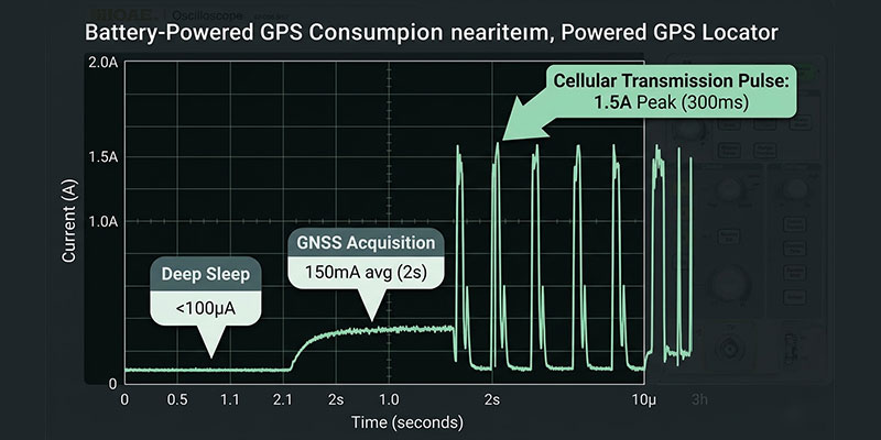
GPS locator current consumption waveform: deep sleep, GNSS acquisition, and cellular transmission pulses up to 1.5A peak

2. Decoding GPS Locator Power Consumption: What 1A/1.5A Actually Covers

A typical GPS locator combines GNSS positioning with cellular reporting (GSM 2G, LTE-M, or NB-IoT). It operates in a duty-cycled pattern. Most of the interval, it stays in deep sleep, consuming microamps. Then it wakes to acquire a fix. That fix takes 50–200mA for 1–5 seconds. Next, it transmits via cellular, typically drawing 500mA–1.5A for 200–500ms. The 1.5A peak rating is specifically sized to cover the worst-case cellular transmission burst — a device attempting registration on a weak GSM signal can transiently demand 1.5A or more. If the protection board’s peak threshold is set too low, it disconnects the battery at exactly the moment the device needs it most.

The 1A continuous discharge rating covers GNSS acquisition and processing, and provides thermal safety margin for sustained operation in enclosed installations where ambient temperature may reach 50–60℃. At these temperatures, a 1A continuous current through a 45mΩ cell produces approximately 45mW of internal heat. This heat is manageable within the thermal budget of a properly designed single-cell pack. Nevertheless, engineers must explicitly check this parameter.

Runtime estimation requires an energy-based model. Assume a 60-second GPS reporting interval. That interval includes 2 seconds of GNSS acquisition at 150mA. It also includes 300ms of cellular transmission at 1.2A average. The remaining 57.7 seconds are deep sleep at 20mA. Under these conditions, the average current is approximately 50–70mA. At 60mA average, a 3400mAh cell provides roughly 56 hours of continuous operation — consistent with the 2–3 day typical service interval quoted in commercial GPS locator product sheets.


3. PCM Design: Why a Circular Protection Board at the Discharge End Is the Right Architecture

The specification calls for a circular protection board placed at the discharge end of the 18650 cell, with cutoff voltage set at 3.0V discharge and 4.2V charge. A circular PCM sized to the 18650 cross-section (~18.5mm diameter) integrates cleanly with the blue PVC heat-shrink packaging. Why choose a circular form? It places the PCB coplanar with the cell’s negative terminal. There, protection MOSFETs and sense resistors have direct thermal contact with the cell can. This arrangement facilitates passive heat transfer toward the cooler exterior. As a result, it avoids trapping heat between the cell and the PCB.

The over-discharge cutoff at 3.0V is deliberately conservative relative to the cell’s absolute minimum (~2.5V). Operating the Samsung 35E below 3.0V under load accelerates lithium plating on the graphite anode. This causes measurable capacity fade within 100 cycles. Therefore, the 3.0V cutoff protects calendar life in GPS locators. These devices may experience extended discharge events without scheduled recharging. The over-charge cutoff at 4.2V is the standard maximum for NMC chemistry; exceeding 4.25V initiates irreversible cathode oxidation and is the primary cause of cell swelling failures.

The Molex 0510210200 (2-pin, 1.25mm pitch) connector with crimped terminal (PN: 0500798000) represents a defined interface rather than a generic JST-style connector. The Molex Pico series is rated for 1A per contact with defined insertion/withdrawal force and retention specification — relevant for GPS trackers installed and removed from vehicle OBD ports or magnetic mounting fixtures multiple times over their operational life.


4. Wire Specification: Why 28AWG at 70mm Is a System-Level Constraint

28AWG copper wire has a resistance of approximately 213mΩ/m. At a total length of 70mm (both conductors), the combined resistance contribution is about 30mΩ. This value is measurable against the cell’s 45mΩ internal resistance and contributes to the total voltage drop during peak transmission events. At 1.5A peak, this 30mΩ produces a 45mV additional voltage drop that the system designer must budget for in minimum operating voltage calculations.

The 28AWG rating also defines current-carrying capacity: at 1.5A continuous, 28AWG copper with standard PVC insulation operates well within its thermal rating for short bundled runs in free air. The specification is intentionally derated. In other words, 28AWG could carry higher currents. However, specifying it at 1A/1.5A provides safety margin. It also keeps wire temperature rise below the PVC insulation thermal limit in the enclosed installation environment of a GPS locator housing.

The 70mm length including connector provides adequate routing slack for strain relief without creating excess length that must be folded and compressed inside the housing. Folded wire is a common source of insulation abrasion failures in high-vibration vehicle installations. OEM device designers should treat the 70mm specification as a mechanical interface requirement, not a rough guide.

Circular protection circuit board (PCM) placed at the discharge end (negative terminal) of an 18650 cell for GPS tracker battery pack

5. Label Compliance and Shipping Requirements for the US Market

The label specification declares: INR18650-35E 3.6V 3400mAh 12.24Wh, with charging and discharging currents stated. These data fields are required by US DOT Hazardous Materials Regulations (49 CFR Part 173) for lithium battery transport. They also align with IEC 62620 labeling requirements for secondary lithium cells in industrial applications.

The 12.24Wh declaration is the key transport classification threshold. Under IATA Dangerous Goods Regulations and 49 CFR §173.185, lithium-ion cells with Wh ≤20Wh qualify for transport as Section II lithium batteries — the most permissive classification, requiring no dangerous goods declaration for most air freight scenarios. The Samsung 35E at 12.24Wh falls comfortably within this threshold. For an order of 11,000 units, correctly classifying the battery at ≤20Wh per cell avoids a freight compliance problem that could delay an entire production delivery.

The 50% SoC requirement for shipping balances three competing requirements: (1) the cell must have enough charge to power the device for incoming inspection; (2) the cell must not be at full charge, where any fault during transit releases maximum energy; and (3) storage at 50% SoC minimizes anode lithium plating and capacity fade during the weeks or months the battery may spend in transit and warehouse storage before integration. The factory registration code on the label (Made in China 31500001…0200) provides traceability required for Chinese lithium battery export declaration under customs HS code 8507.60.


6. Application Context: GPS Locator Power Architecture Considerations for OEM Designers

For OEM engineers integrating this battery into a GPS locator product targeting the US market, several system-level decisions flow directly from the battery specification:

Charger Design

The 1A maximum charge current and 4.2V charge voltage define the CC/CV charger specification. IEC 61960 requires that chargers follow battery manufacturer parameters and only initiate charging within a safe temperature window (typically 0–45℃ for NMC). A charger that ignores cell temperature and charges at 1A in a -10℃ environment will cause lithium plating regardless of the PCM’s voltage-based protections — temperature-aware charging is a firmware requirement, not only a hardware one.

Connector Interface

The Molex 0510210200 (2-pin) connector provides battery voltage only — no SMBus, no thermistor output, no authentication. If the end device requires battery SoC estimation (fuel gauge), this must be implemented on the device PCB using a coulomb-counting IC (e.g., Texas Instruments BQ27427) with the battery connected through a known sense resistor. Alternatively, the battery design can be upgraded to include a 3-wire or 4-wire connector with thermistor and authentication outputs — a common next-step request as GPS locator OEMs add fleet management features.

Housing Thermal Design

A blue PVC-wrapped 18650 in a sealed GPS locator housing creates a thermal resistance path that matters at sustained 1A discharge. At 60℃ ambient (parked vehicle in summer), the combination of elevated ambient and internal heat generation can push cell temperature toward 70–75℃ during sustained transmission events. NMC cells operated above 60℃ sustained exhibit accelerated SEI layer growth and capacity fade. Good GPS locator housing design includes a thermal path — such as the cell in contact with an aluminum housing wall — that limits steady-state cell temperature to below 55℃ even at maximum rated ambient.

GPS locators are a key segment of the broader Internet of Things (IoT) ecosystem. For designers working on other battery-powered IoT devices — such as asset trackers, environmental sensors, or smart logistics tags — similar engineering principles apply. Explore our IoT battery solutions page to see how we optimize cell selection, PCM architecture, and connectivity for low-power wide-area network (LPWAN) and cellular IoT applications.

28AWG wire (70mm) with Molex 0510210200 2-pin connector for GPS locator battery assembly

Product Specification Summary

Parameter Value
Cell Model Samsung INR18650-35E
Configuration 1S1P
Nominal Voltage 3.6V
Rated Capacity 3400mAh
Energy 12.24Wh
Charged Voltage 4.2V
Discharged Cutoff Voltage 3.0V
Max Charging Current 1A
Max Discharging Current 1A continuous, 1.5A peak
Wire Spec 28AWG, 70mm including connector
Connector (plug) Molex 0510210200
Connector (crimp terminal) PN 0500798000
Protection Board Circular PCM, discharge-end placement
Packaging Blue PVC heat shrink
Shipping SoC 50%
Order Quantity 11,000 units
Primary Application GPS locator (US market)
Delivery Requirement 2026-06-22


Need a Custom GPS Locator Battery Solution?

Whether you require a different capacity, a specific connector, or an integrated fuel gauge for your IoT tracking device, our engineering team can tailor the design to your exact specifications. We support OEM/ODM projects from prototype to mass production — including full documentation for US DOT, IATA, and IEC compliance.

Contact our battery engineers to discuss your GPS locator power requirements, request samples, or receive a compliance package for your next product launch.

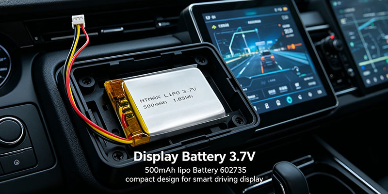
Display Battery 3.7V 500mAh lipo Battery 602735 compact design for smart driving display


As Nath, a Battery Engineer with over 10 years of experience at Himax Electronics, I’ve spent most of my career solving one specific challenge: how to design the right Display Battery for demanding applications like intelligent driving display systems.

If you are a smart driving display manufacturer or a B2B procurement professional, you already understand the pressure. You need a stable, scalable, and cost-effective battery supply, while ensuring your product remains compact, reliable, and safe. That’s not an easy balance—but it’s absolutely achievable with the right approach.

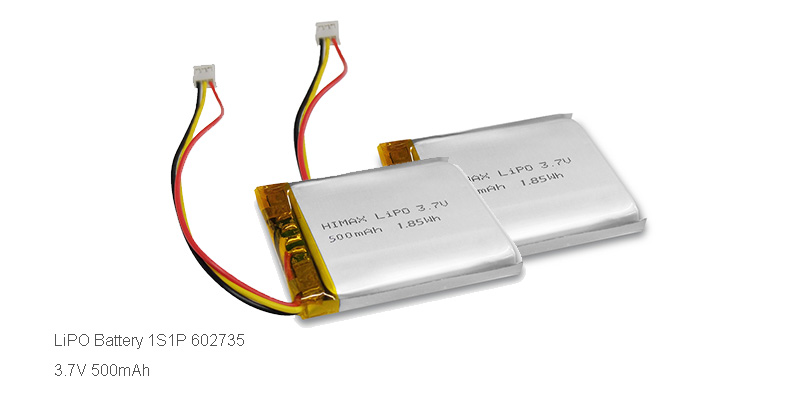
In this article, I’ll walk you through how a custom Display Battery solution, specifically based on a lipo Battery 3.7V 500mAh (1S1P 602735, NMC chemistry), can directly solve your key pain points—especially when it comes to compact size, long runtime, and safety.

Why Custom Display Battery Solutions Matter for Smart Driving Displays

Let me be direct: off-the-shelf batteries rarely meet the real-world demands of smart driving displays.

These systems are unique. They operate in constrained spaces, require stable power delivery, and must perform consistently over time. That’s why a custom Display Battery is not a luxury—it’s a necessity.

Key Challenges Faced by B2B Buyers

From my experience working with procurement teams, here are the most common issues:

  • Supply chain instability
  • Inconsistent battery quality
  • Mismatch between battery size and device structure
  • Poor discharge performance under peak loads
  • Safety concerns in enclosed environments


A well-designed Battery for the smart driving display addresses all of these issues systematically.

What Customization Really Means

When I talk about customization, I don’t just mean changing dimensions. I mean:

  • Matching capacity to actual power consumption
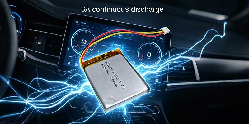
  • Optimizing discharge current (up to 3A continuous)
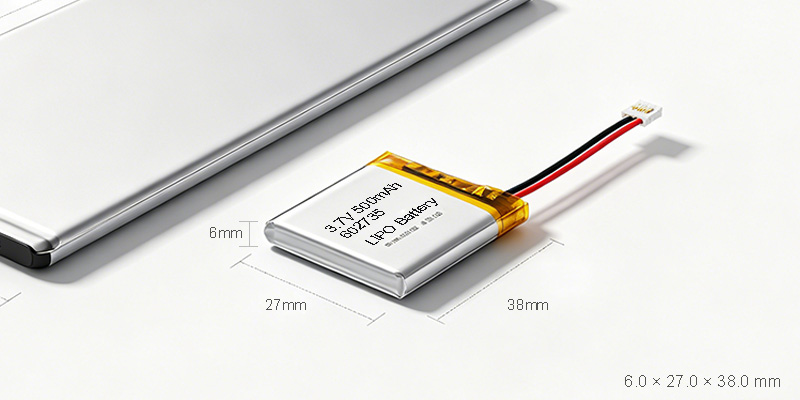
  • Ensuring mechanical compatibility (6.0 × 27.0 × 38.0 mm)
  • Integrating protection circuits for safety


This is where a Display Battery becomes a solution—not just a component.

Battery for the smart driving display installed in intelligent driving screen module

Compact Size: Engineering for Space-Constrained Designs

Let’s talk about size. Every millimeter matters in smart display design.

The 602735 lipo Battery is engineered specifically for compact environments:

  • Thickness: 6.0 mm
  • Width: 27.0 mm
  • Length: 38.0 mm


Why Compact Matters

A smaller battery enables:

  • Slimmer product design
  • Better internal layout flexibility
  • More room for key components like processors and sensors


From a design perspective, this is critical.

My Engineering Approach

When optimizing a Display Battery, I focus on:

  • Energy density optimization(maximizing capacity within limited volume)
  • Thermal management compatibility
  • Mechanical stability under vibration


The NMC chemistry used in this lipo Battery provides an excellent balance between energy density and stability, making it ideal for compact smart display applications.

Practical Benefits for Buyers

For B-end procurement teams:

  • Easier integration into multiple product models
  • Reduced redesign costs
  • Faster time-to-market


This is exactly why a tailored Battery for the smart driving display creates long-term value.

Long Runtime: Meeting Real-World Usage Demands

Ultra thin Display Battery 602735 size comparison showing compact lipo Battery design

Now let’s move to one of the most critical performance metrics—runtime.

A 500mAh capacity may seem modest on paper, but when properly optimized, it delivers surprisingly strong endurance.

What Determines Runtime?

In a Display Battery, runtime depends on:

  • Device power consumption
  • Discharge efficiency
  • Voltage stability
  • Load variation


The Lipo battery 3.7V, 500mAh for intelligent driving display screen is designed to handle these factors effectively.

Performance Highlights

  • Nominal Voltage: 3.7V
  • Capacity:500mAh
  • Continuous Discharge: 3A


This means the battery can:

  • Support high-brightness displays
  • Handle peak processing loads
  • Maintain stable performance over time


Why It Matters for Your Business

Longer runtime leads to:

  • Better user experience
  • Reduced charging frequency
  • Lower maintenance costs


For B2B buyers, this translates into higher product reliability and fewer after-sales issues.

Safety First: A Non-Negotiable Requirement

Let’s be honest—battery safety is not optional, especially in smart driving environments.

A Display Battery must meet strict safety standards, particularly when integrated into enclosed systems.

Key Safety Features

The lipo Battery (NMC chemistry) includes:

  • Stable chemical structure
  • Built-in protection circuit compatibility
  • Controlled discharge behavior
  • Low internal resistance


My Safety Design Philosophy

When designing a Battery for the smart driving display, I always prioritize:

  • Overcharge protection
  • Over-discharge protection
  • Short circuit protection
  • Thermal stability


Risk Reduction for Buyers

A safe battery solution helps you:

  • Avoid product recalls
  • Reduce liability risks
  • Build brand trust


The Lipo battery 3.7V, 500mAh for intelligent driving display screen is engineered with these principles in mind.

lipo Battery Optimization for Smart Driving Displays

This is where things get interesting—and where engineering truly makes a difference.

Why Choose a lipo Battery?

A lipo Battery offers several advantages:

  • High energy density
  • Flexible form factor
  • Lightweight design
  • Stable discharge characteristics


Optimization Strategies

When I work on a Display Battery, I focus on:

  • Reducing internal resistancefor better efficiency
  • Improving cycle lifethrough material selection
  • Enhancing discharge curvesfor stable output


Real-World Impact

For smart driving displays:

  • Smooth screen performance
  • No sudden shutdowns
  • Consistent brightness levels


This is why a properly optimized Battery for the smart driving display outperforms generic solutions.

Supply Chain Stability: What B2B Buyers Really Care About

Let’s shift from engineering to business reality.

For procurement teams, performance is only half the story. The other half is supply chain reliability.

Common Supply Issues

  • Inconsistent batch quality
  • Long lead times
  • Lack of technical support
  • Poor communication


How We Address Them

At Himax Electronics, we focus on:

  • Standardized production processes
  • Strict quality control systems
  • Reliable delivery schedules
  • Technical collaboration with clients


Why It Matters

A stable Display Battery supply chain ensures:

  • Predictable production planning
  • Reduced risk of delays
  • Stronger business continuity


And let’s face it—that’s exactly what B-end buyers are looking for.

ipo battery 3.7V 500mAh for intelligent driving display screen stable discharge performance

Application Case: Smart Driving Display Integration

Let me give you a practical perspective.

Typical Application Scenario

In a smart driving display:

  • The system runs continuously
  • Space is extremely limited
  • Power demand fluctuates


Why This Battery Works

The Lipo battery 3.7V, 500mAh for intelligent driving display screen delivers:

  • Compact integration
  • Stable power output
  • Reliable performance under load


Results

  • Improved device reliability
  • Better user experience
  • Reduced service costs


This is the real value of a well-designed Display Battery.

How I Help Clients Choose the Right Display Battery

Over the years, I’ve developed a structured approach to battery selection.

Step-by-Step Process

1. Analyze application requirements

2. Evaluate power consumption profile

3. Match battery specifications

4. Optimize design and integration

5. Validate performance through testing


What You Get

  • A tailored Battery for the smart driving display
  • Optimized performance
  • Reduced risk


This process ensures that your Display Battery is not just functional—but truly optimized.

Conclusion: The Right Display Battery Makes the Difference

In the world of smart driving displays, the battery is more than a power source—it’s a critical performance driver.

By focusing on:

  • Compact size
  • Long runtime
  • Safety
  • Supply chain stability


A custom Display Battery solution can solve your biggest challenges.

The Lipo battery 3.7V, 500mAh for intelligent driving display screen is a perfect example of how engineering and practical design come together to create real value.

If you’re serious about improving your product performance and ensuring supply reliability, then it’s time to rethink your battery strategy.

Call to Action

If you’re a smart driving display manufacturer or B2B buyer looking for a high-quality, cost-effective Display Battery solution, I’m here to help.

Contact us today to customize your battery solution and secure a stable, reliable supply for your next project.


Author: Nath, Battery Engineer – Cell Selection & Performance
Published: April 14th, 2026

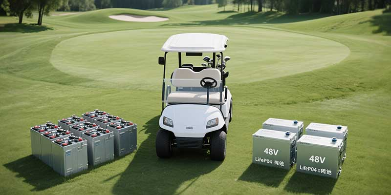
48v golf cart upgrade

Upgrading your golf cart’s powertrain from traditional lead‑acid batteries to a 48V LiFePO4 battery pack isn’t just about squeezing out a few extra miles—it’s about transforming maintenance headaches, total cost of ownership, and day‑to‑day peace of mind. In this post, we’ll walk through a detailed ROI model, comparing upfront costs, maintenance expenses, and real‑world range gains. Plus, we’ll show you how to add a zero‑code ROI calculator right in your WordPress post so readers can instantly see their own payback period.


1. Why Upgrade Your 48V Golf Cart Battery?

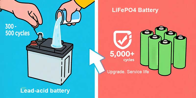
Anyone who’s wrestled with heavy lead‑acid blocks or topped off water cells under the seat knows the drawbacks: frequent maintenance, voltage sag under load, and just 300–500 charge cycles. Switching from lead‑acid to lithium (LiFePO4) changes everything:

– Longer Lifespan: LiFePO4 packs deliver 3,000+ cycles—up to five times that of deep‑cycle lead‑acid.

– Weight Savings: Drop 50%–70% of the battery weight for better acceleration and battery tray space.

– Stable Voltage: A flat discharge curve means consistent power until your pack is nearly empty.

– Zero Maintenance: No watering, no equalizing charges, no acid spills.

lead acid to lithium battery

2. Cost Structure: Lead‑Acid vs. 48V LiFePO4

2.1 Upfront Purchase Price

– Lead‑Acid (6×8 V deep‑cycle): $800–$1,500 per 48 V set

– 48V 100 Ah LiFePO4: $1,500–$2,500

2.2 Cost‑Per‑Cycle Comparison

– Lead‑Acid: ~500 cycles → $1,000/500 = $2.00 per cycle

– LiFePO4: ~3,000 cycles → $2,000/3,000 = $0.67 per cycle


3. Maintenance Cycle & Ongoing Costs

3.1 Lead‑Acid Maintenance

– Watering & Equalizing: Every 20–30 cycles you top off distilled water and run an equalizing charge.

– Cost: $50–$100 per year in labor and supplies.

3.2 LiFePO4: True “Fit‑and‑Forget”

– No Watering: Sealed cells, no acid refills.

– No Equalization: Built‑in BMS handles balancing.

– Cost: Virtually zero scheduled maintenance.

lithium battery vs lead acid

4. Range & Efficiency Gains

4.1 Lead‑Acid Range

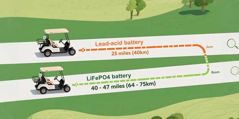
About 25 miles (40 km) on a full charge under moderate load.

4.2 LiFePO4 Range

A 48V LiFePO4 battery (100 Ah) often delivers 40–47 miles (64–75 km), thanks to deeper usable capacity and lower internal resistance.


5. Building an ROI Model & Payback Period

To answer “When will I see a return on investment?” we use:

Payback Period (years) = Cost Difference / Annual Savings

– Cost Difference = Cost LiFePO4 – CostLeadAcid

– Annual Savings = Maintenance + Energy Efficiency Gains

Example:

– Lead‑Acid: $1,000

– LiFePO4: $2,000

– Difference: $1,000

– Maintenance Savings: $80/year

– Energy Savings: $150/year

– Total Savings: $230/year

Payback = $1,000 ÷ $230 ≈ 4.3 years

golf cart lifepo4 battery

7. Conclusion & Next Steps

Switching from lead‑acid to lithium in your golf cart is more than a tech upgrade—it’s a smart financial choice. With the embedded ROI calculator, your readers can immediately see their payback timeline and feel confident investing in a 48V LiFePO4 battery upgrade.

Ready to take the leap? Contact Himax for a custom quote, expert installation, and support every mile of the way.

best-lifepo4-solar-battery

At HIMAX ELECTRONICS, we are a leading lithium-ion battery manufacturer, specializing in high-performance LiPo batteries, LiFePO4 (lithium iron phosphate) batteries, and custom battery solutions for medical devices. With a strong focus on the North American and European markets, we provide safe, long-lasting, and eco-friendly power solutions for critical healthcare applications.

Our LiFePO4 batteries are widely used in portable pulsatile pumps, infusion pumps, and other medical equipment, trusted by top-tier clients such as Becton Dickinson (BD) and other medical device companies.


In this blog, we explore:
✔ Why LiFePO4 batteries are ideal for medical devices (safety, low self-discharge, and structural flexibility)
✔ HIMAX’s competitive advantages (R&D expertise, manufacturing excellence, and superior quality)
✔ Why LiFePO4 is replacing lead-acid batteries in medical applications

Why LiFePO4 Batteries Are the Best Choice for Medical Devices?

Medical devices demand high safety standards, reliability, and long service life. Lithium iron phosphate (LiFePO4) batteries outperform traditional lead-acid and standard lithium-ion batteries in critical ways:


1. Unmatched Safety for Medical Applications

Safety is non-negotiable in medical-grade batteries. LiFePO4 chemistry offers:
✅ Thermal & chemical stability – Unlike other lithium batteries, LiFePO4 does not overheat or explode.
✅ Resistance to overcharging & short circuits – Critical for infusion pumps, portable medical devices, and emergency equipment.
✅ Non-toxic & non-hazardous – Safer for hospitals and disposal compared to lead-acid batteries.


2. Extremely Low Self-Discharge Rate (Longer Shelf Life)

Many medical devices remain in standby mode or storage for extended periods. LiFePO4 batteries excel because:
? Only 1-3% self-discharge per month (vs. 5-20% for lead-acid batteries).
? Maintains charge for years – Ideal for emergency backup power in medical equipment.
? No frequent recharging needed – Reduces maintenance costs.


3. Flexible Design for Custom Medical Devices

Medical equipment comes in various shapes and sizes. LiFePO4 batteries provide:

  • Lighter weight– Up to 70% lighter than lead-acid batteries, improving portability.
  • Compact & customizable shapes– Perfect for wearable medical devices, portable pumps, and handheld diagnostic tools.
  • High energy density– More power in a smaller footprint.

Energy storage lifepo4 battery

HIMAX’s Competitive Edge in Medical-Grade Batteries


✔ Advanced R&D & Custom Battery Solutions

Our in-house R&D team develops bespoke LiFePO4 battery packs tailored for:

  • Infusion pumps
  • Portable dialysis machines
  • Diagnostic devices
  • Wearable medical monitors


✔ State-of-the-Art Manufacturing Facility

We use automated production lines & strict quality control to ensure:

  • High consistency & reliability
  • Compliance with FDA, CE, RoHS, and UN38.3 standards
  • ISO-certified manufacturing processes


✔ Trusted by Leading Medical Device Companies

Our clients include Becton Dickinson (BD) and other top-tier medical manufacturers, proving our reputation for:

  • Long-lasting battery life (2000+ cycles)
  • Zero safety incidents
  • On-time global delivery

Why LiFePO4 is Replacing Lead-Acid Batteries in Medical Devices?

Despite their historical use, lead-acid batteries are being phased out due to:

❌ Environmental hazards – Contain toxic lead & sulfuric acid.
❌ Short lifespan – Only 300-500 cycles vs. 2000+ for LiFePO4.
❌ Heavy & bulky – Not suitable for modern portable medical devices.

LiFePO4 batteries offer a cleaner, more efficient, and longer-lasting alternative, making them the future of medical power solutions.

lifepo4 battery 12V

Conclusion: Powering the Future of Medical Devices with HIMAX ELECTRONICS

At HIMAX ELECTRONICS, we are committed to innovative, safe, and high-performance battery solutions for medical applications. Our LiFePO4 batteries provide:
✔ Superior safety for critical healthcare equipment
✔ Ultra-low self-discharge for reliable long-term use
✔ Custom designs for any medical device


Partner with HIMAX ELECTRONICS CO LTD for premium lithium batteries that meet the highest industry standards.


Contact us to learn how HIMAX ELECTRONICS can enhance your medical equipment with superior battery technology!

custom_solar_batteries
In recent years, the global energy transition has accelerated, and solar energy has become one of the most viable renewable energy sources. Solar power systems, however, require efficient energy storage solutions to ensure a continuous and reliable power supply, especially during non-sunny periods. This is where custom batteries come in—designed specifically to meet the energy demands of solar energy systems.
In this guide, we’ll explain how to design the perfect custom battery for your solar energy system, covering everything from understanding your system’s needs to selecting the right battery type and optimizing for safety, efficiency, and longevity.
LiFePO4_battery

Understanding the Energy Needs of Your Solar System

The first step in designing a custom battery for your solar energy system is understanding your power requirements. Without a proper understanding of these needs, it’s impossible to select the right battery type, size, and capacity.
1. Assess Your Energy Consumption
To begin, evaluate the energy consumption of your home or business. This includes looking at your daily energy usage patterns and understanding peak demand times. Review your monthly electricity bills to find out how much energy you use on average each day. You can also use energy monitoring devices to get a more accurate real-time breakdown of your consumption.
2. Calculate Battery Capacity
Once you have a sense of your energy usage, you need to determine the appropriate battery capacity. Battery capacity is typically measured in kilowatt-hours (kWh). To calculate this, you need to consider how long you want your battery to provide power when solar generation isn’t available (e.g., during the night or cloudy days).
For example, if your daily energy consumption is 30 kWh and you want your battery to last for one full day of backup, you’d need a battery that has at least 30 kWh of storage capacity.
3. Consider Peak Power Demand
In addition to storing enough energy, the battery should be capable of handling your peak power demand. This is especially important for devices or appliances that use a lot of energy in a short burst (e.g., HVAC systems, refrigerators, or washing machines). You’ll need to select a battery system that can supply high discharge rates when required.

Choosing the Right Type of Battery for Your Solar System

When selecting a battery, it’s essential to understand the various types available, each of which has its own advantages and disadvantages. Below, we’ll break down some of the most commonly used battery types for solar energy systems.
1. Lithium-ion (Li-ion) Batteries
Lithium-ion batteries, including the popular LiFePO4 battery (Lithium Iron Phosphate), have become a go-to option for modern solar energy storage systems. Li-ion batteries are well known for their high energy density, lightweight design, and long cycle life. These batteries are also safer and more efficient than traditional options like lead-acid batteries.
LiFePO4 batteries, specifically, are an excellent choice for solar applications due to their thermal stability, non-toxic nature, and long-lasting performance. They are highly efficient, typically offering a lifespan of 10+ years with minimal degradation, which makes them a great investment in the long term.
2. Lead-acid Batteries
Lead-acid batteries have been around for decades and are often seen as a cheaper alternative to lithium-ion batteries. They are available in two types: flooded lead-acid and sealed (AGM and Gel). While they are cheaper upfront, they have a shorter lifespan, lower efficiency, and a slower charging time compared to lithium-ion batteries. Lead-acid batteries are also more prone to overcharging and require more maintenance.
3. Saltwater Batteries
Saltwater batteries are an emerging option that uses a mixture of saltwater and other materials to store energy. These batteries are known for being environmentally friendly and less toxic compared to lithium-ion and lead-acid batteries. However, they are still relatively new to the market and may not yet have the efficiency and longevity of other battery types, making them less common for solar installations.
4. Flow Batteries
Flow batteries use a different method for storing energy, where a liquid electrolyte flows through a system to release stored energy. While these batteries are efficient for larger-scale applications and offer long-duration energy storage, they are often too expensive and complicated for typical residential solar systems.

Key Factors to Consider When Designing a Custom Battery

Designing the perfect custom battery involves more than simply choosing the right battery type. Several other factors must be considered to ensure that your battery system is optimized for both performance and safety.
1. Battery Capacity and Voltage
Choosing the right capacity is crucial. As we mentioned earlier, you’ll need to calculate how much energy storage you need based on your consumption. You’ll also need to decide on the right voltage for your system. Solar energy systems typically run on either 12V, 24V, or 48V systems, and the battery you choose must be compatible with these voltages.
2. Battery Management System (BMS)
A Battery Management System (BMS) is critical to ensuring that your battery operates efficiently and safely. The BMS helps monitor the voltage, current, and temperature of the battery and prevents issues like overcharging or overheating, which can lead to battery failure. When designing a custom battery system, make sure your battery is equipped with a reliable BMS to maximize safety and performance.
3. Cycle Life and Warranty
The lifespan of your battery will have a significant impact on its cost-effectiveness. Batteries have a limited number of charge/discharge cycles, after which they begin to degrade. Lithium-ion batteries like LiFePO4 offer an impressive cycle life—up to 3,000 cycles or more—ensuring that your battery lasts for many years with minimal degradation. Be sure to check the warranty period as well, as a longer warranty is often indicative of better battery quality.
4. Efficiency and Depth of Discharge (DoD)
Efficiency refers to the amount of energy that can be extracted from the battery compared to the amount of energy used to charge it. A high-efficiency battery means that less energy is lost during charging and discharging cycles.
Depth of Discharge (DoD) refers to how much of the battery’s capacity can be used before it needs to be recharged. For example, a battery with an 80% DoD means you can use up to 80% of the battery’s capacity before recharging. A higher DoD generally means more usable energy, but it can shorten the overall lifespan of the battery. LiFePO4 batteries typically allow for a deeper discharge (up to 90%) without significantly impacting lifespan.
5. Temperature Tolerance and Ventilation
Temperature extremes can impact battery performance and lifespan. High temperatures can cause batteries to degrade faster, while cold temperatures can reduce the battery’s efficiency and overall performance. Ensure that your battery design accounts for temperature tolerance and includes appropriate ventilation or thermal management systems, especially in regions with extreme weather conditions.
6. Safety Features
Safety is paramount when designing a custom battery for solar energy. Look for batteries with built-in safety features like overcurrent protection, thermal protection, and short-circuit protection. These features help prevent battery failures and ensure long-term safety. LiFePO4 batteries, for example, are known for their inherent safety and stability, making them a top choice for solar applications.

Testing and Integration: Ensuring the Battery System Works Seamlessly with Your Solar Setup

Once you’ve chosen and designed your custom battery, it’s time to integrate it into your solar energy system. Before final installation, it’s essential to perform tests to ensure that the battery performs as expected under different load and environmental conditions. This includes checking the battery’s efficiency, charge/discharge rates, and response to temperature changes.
Make sure that your battery system is compatible with the rest of your solar energy system—this includes your solar panels, inverter, and any other power management equipment. If necessary, consult a professional installer to help ensure that all components work together seamlessly.
solar_energy_storage

Himax Electronics: Your Partner for Custom Battery Solutions

At Himax Electronics, we specialize in providing high-quality, customized battery solutions for solar energy systems. Our LiFePO4 battery products are designed with advanced technology to deliver superior performance, efficiency, and longevity. With a focus on safety and reliability, we ensure that our batteries are tailored to meet the unique needs of your solar system.
Whether you’re a homeowner or a business owner looking to optimize your solar energy storage, Himax Electronics offers flexible solutions to fit your specific requirements. Our team of experts can assist you in designing a custom battery that aligns perfectly with your energy needs and budget.

Conclusion

Designing the perfect custom battery for your solar energy system requires careful consideration of your energy needs, the right battery type, and several technical factors. By selecting the best-suited battery and ensuring it’s properly designed, you can achieve an efficient, reliable, and long-lasting solar energy storage system.
If you’re ready to take the next step in enhancing your solar energy system, Himax Electronics is here to provide you with the high-quality, customized battery solutions you need to maximize your system’s performance. Reach out to us today to discuss your specific requirements and discover the perfect battery for your solar system.
Battery_supplier_choose

A team of engineers, chemists and materials scientists at Stanford University, has found that applying short duration voltage to some types of anodes in Li–Si batteries, can restore some of their capacity. In their paper published in the journal Science, the group describes how they experimented with batteries by applying an electrical charge to several types of silicon anodes.

Chengbin Jin and Xinyong Tao, both with Zhejiang University of Technology, in China, have published a Perspective piece in the same journal issue outlining the work done by the team.

It is common knowledge that lithium-ion batteries do not last very long. After multiple charge/recharge cycles, the batteries begin to hold less and less charge until they become of little use and replacement becomes necessary. Because of that, some battery makers have begun to look into the possibility of using silicon anodes.

This idea may grow in popularity since the team at Stanford has found that for some types of Li-ion batteries, giving them a five-minute burst of electricity directly to the anode can restore some capacity.

Batteries that have a silicon anode have a higher density than those made using other materials, which increases their capacity. Unfortunately, upon use, some of the silicon begins to fragment, which reduces capacity. This is because the fragmenting creates isolated chunks of silicon that are partly filled with lithium—they are like little islands, unusable for holding charge.

In this new study, the research team found that applying electricity directly to the anode pulled some of the isolated chunks back to the anode, making them able to hold a charge again. After testing anode charging, the researchers tested batteries that had pure silicon anodes. Applying electricity directly to their anodes led to some degree of restored capacity.

During their experiments, the researchers found that the more electricity they applied, the more capacity was restored, but there was a limit. Too much electricity led to degradation of the electrolyte. They also found that varying the length of time that voltage was applied had an impact on restoration of capacity. Eventually, they found that applying four volts for five minutes gave the best result—a 30% increase in capacity.

More information: Yufei Yang et al, Capacity recovery by transient voltage pulse in silicon-anode batteries, Science (2024). DOI: 10.1126/science.adn1749

Chengbin Jin et al, Electric pulses rejuvenate batteries, Science (2024). DOI: 10.1126/science.ads9691

Journal information: Science


Life-cycle-of-a-ternary-lithium-battery

Rechargeable aqueous zinc-iodine batteries get a lot of attention because they are safe, do not cost much, and have a high theoretical capacity. Zinc has a high theoretical capacity (820 mAh g-1) and iodine is found in large amounts in the Earth’s crust. However, the limited cycle life of zinc-iodine batteries remains a significant challenge for their market viability.

The thermodynamic instability of the zinc electrode in an aqueous electrolyte always leads to the release of hydrogen, which causes the battery to swell and eventually fail. In addition, in aqueous electrolytes, reversible redox reactions often occur at the iodine cathode, involving triiodide, iodide, and polyiodide (I3-/I-/I5-). The ZnO and Zn(OH)42- passivation layers may further interact with triiodide and exacerbate the adverse effects on the zinc anode. Therefore, mitigating these parasitic side reactions on the zinc surface is essential to achieve a long-life rechargeable ZnI2 battery.

The researchers reported a new class of fluorinated block copolymers as solid electrolytes for the development of all-solid-state ZnI2 batteries with extended lifespan. The results of the study suggest that the zinc metal anode circulating in this solid electrolyte forms a stable fluoride-rich SEI layer, which promotes the deposition of zinc in the horizontal direction and prevents the growth of harmful zinc dendrites that can damage the separator and cause battery failure.

In addition, this solid electrolyte effectively relieves the I3- shuttle problem extending the battery lifetime. Symmetrical cells assembled with this solid electrolyte are stably plated and stripped for about 5,000 hours at 0.2 mA cm-2. The complete ZnI2 battery has a longer rating of 0.5 C, impressive rate performance, and nearly 100% coulombic efficiency for more than 7,000 cycles (over 10,000 hours). The electrolyte exhibits excellent rate performance, delivering a reversible capacity of 79.8 mAh g-1 even at ultra-high current densities of 20 C.

These results highlight the great commercial potential of this all-solid-state battery. This study opens a new avenue for the design of fluorosolid-state polymer electrolytes for next-generation ZnI2 batteries with dendricity-free Zn metal anodes and ultra-long battery life.


Fast-charging-batteries

Future research will explore more practical application scenarios of this battery while controlling costs. This solid-state ZnI2 battery featuring the solid perfluoropolyether (PFPE)-based polymer electrolyte demonstrates the formation of a solid electrolyte interphase (SEI) layer on zinc, promoting horizontal zinc growth, mitigating dendrite penetration, and enhancing battery cycle life.

Moreover, the solid electrolyte hinders the iodine ion shuttle effect, reducing zinc foil corrosion. Symmetric batteries employing this electrolyte demonstrate excellent cycle performance, maintaining stability for approximately 5,000 hours at room temperature, while solid-state ZnI2 batteries exhibit over 7,000 cycles with a capacity retention exceeding 72.2%.

This work offers a promising pathway to achieving reliable energy storage in solid-state ZnI2 batteries and introduces innovative concepts for flexible and wearable zinc batteries.

The research is published in the journal Materials Futures.

More information: Yongxin Huang et al, Enhancing Performance and Longevity of Solid-State Zinc-Iodine Batteries with Fluorine-Rich Solid Electrolyte Interphase, Materials Futures (2024). DOI: 10.1088/2752-5724/ad50f1

Provided by Songshan Lake Materials Laboratory