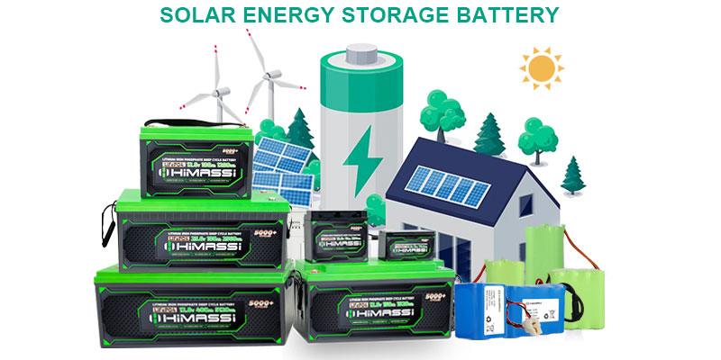
A solar garden light battery endures a tough life. It sits outside through rain, frost, and summer heat. It charges daily from a small solar panel. And it must power lights every night for years—all without any maintenance. This challenge is fundamentally a power system design problem, not merely a bill-of-materials exercise. For this reason, more lighting OEMs are standardizing on a 12.8V 24Ah LiFePO4 battery pack for their outdoor fixtures.
Why Solar Garden Lights Need a Reliable LiFePO4 Battery
Unlike a backup battery that sits idle, a solar garden light battery cycles every day. It charges during daylight hours and discharges overnight to power LEDs and sensors. Therefore, over a multi-year installation, the cycle count adds up fast across 365 nights each year. Consequently, both the battery chemistry and its protection circuit must support this demanding duty cycle from the start. They cannot be simple adaptations from a device designed for occasional use.
The Real-World Demands on a Solar Garden Light Battery
Daily Deep-Cycle Charging From a Small Solar Panel
Garden light solar panels are compact. As a result, charging current is modest, and charge time often stretches across a full day. For this reason, the battery needs efficient charge acceptance at low current. Moreover, the charge controller and BMS must manage the transition from bulk charging to a safe float voltage, ensuring they waste as little of the panel’s limited energy as possible.
Outdoor Exposure: Rain, Humidity, and Temperature Swings
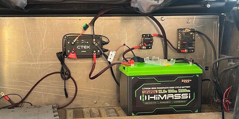
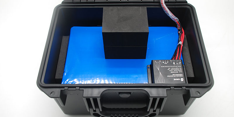
Garden and pathway lighting operates outdoors year-round. Therefore, the battery enclosure must resist moisture ingress. Similarly, the internal cell chemistry must tolerate summer heat and winter cold without losing capacity or safety margin. Thus, an IP-rated case paired with a wide operating temperature range is the baseline requirement, not an upgrade.
Years of Maintenance-Free Service
No one wants to dig up a pathway light fixture just to swap a battery every season. A pack rated for thousands of shallow cycles with low monthly self-discharge ensures long-term, reliable performance. This protects the end user’s experience and, in turn, helps the OEM control warranty costs.
Why LiFePO4 Outperforms Lead-Acid and Standard Li-ion
Longer Cycle Life, Lower Total Cost of Ownership
LiFePO4 cells typically deliver more than 2,000 cycles at 100% depth of discharge. This represents roughly 20 times the cycle life of a comparable lead-acid battery. For a daily-cycling product, this difference determines whether the battery outlasts the fixture or becomes its weakest link.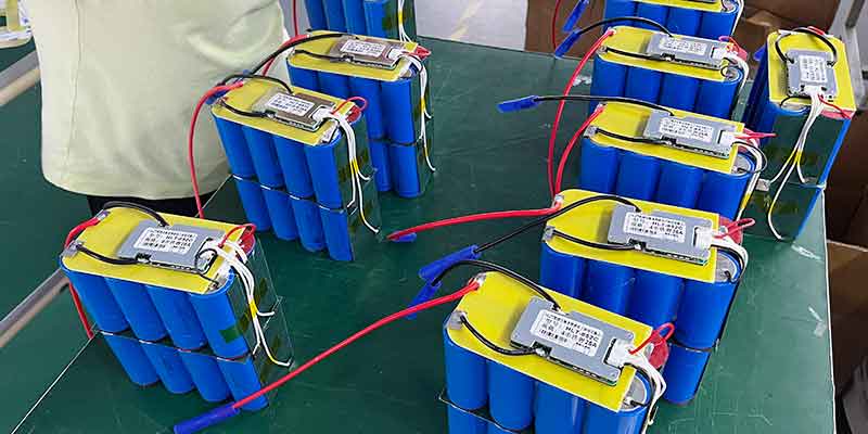
Lighter Weight, Easier Installation
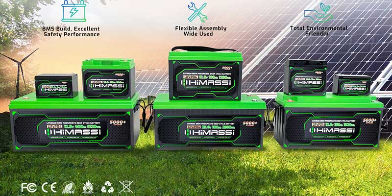
A LiFePO4 pack weighs only about 40% as much as an equivalent lead-acid battery. This makes it easier to ship, install, and mount inside a compact light housing. This weight advantage is particularly valuable for OEMs retrofitting existing lead-acid designs into a lighter, longer-lasting platform.
Built-In Safety Under Outdoor Conditions
Lithium iron phosphate chemistry is inherently more thermally stable than other lithium-ion chemistries. This stability lowers the risk of thermal runaway from overcharging, short circuits, or physical impact—all realistic scenarios for a battery exposed to the elements in an outdoor fixture.
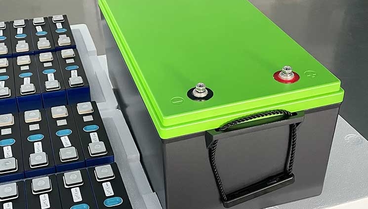
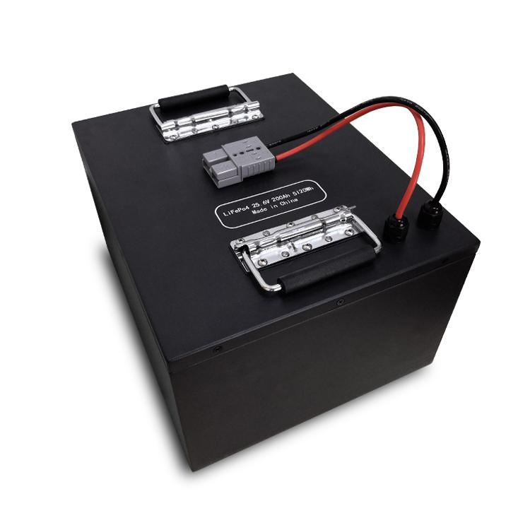
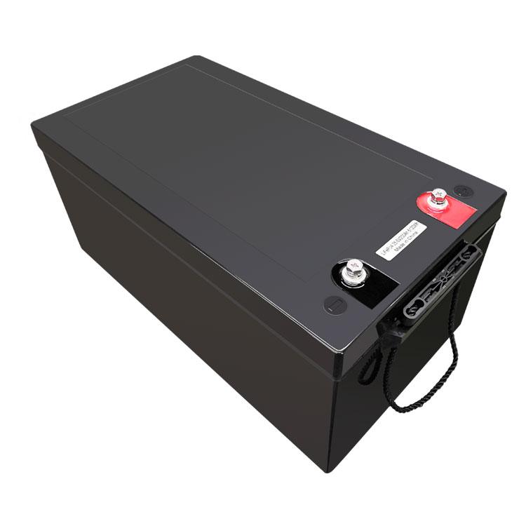
Inside a 12.8V 24Ah LiFePO4 Battery Pack
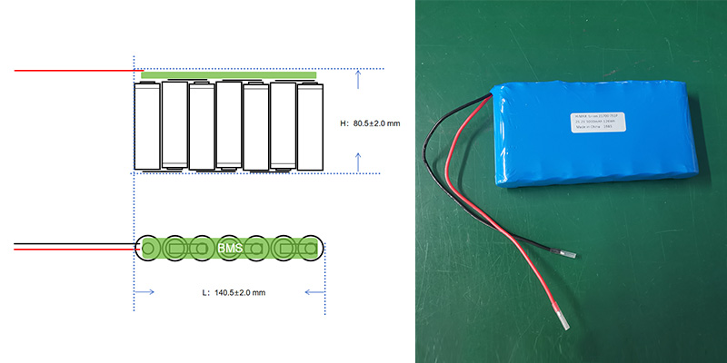
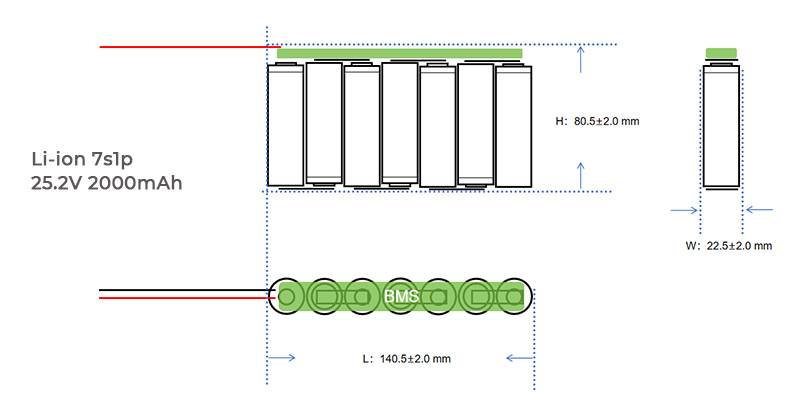
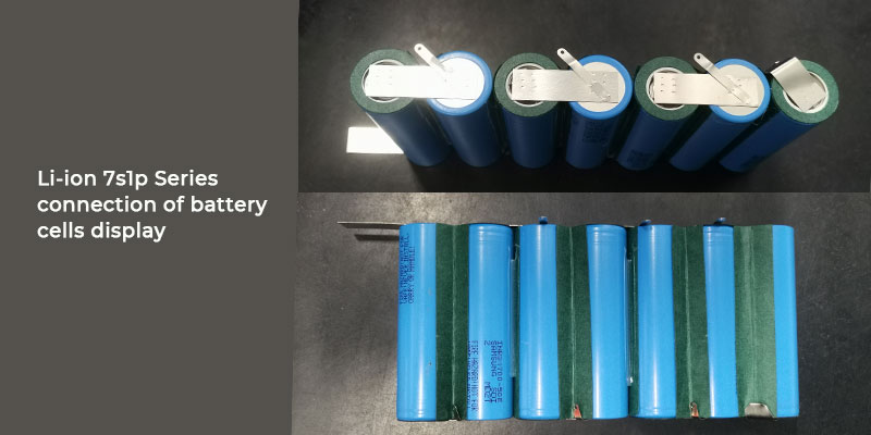
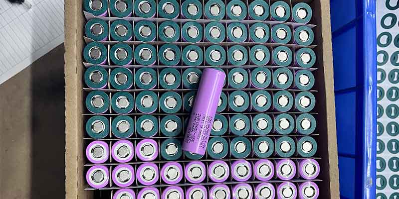
A pack designed for this application typically uses four LiFePO4 cells in series (4S). This configuration delivers a nominal 12.8V output at 24Ah, which perfectly matches the voltage window most solar garden light drivers and LED controllers use.
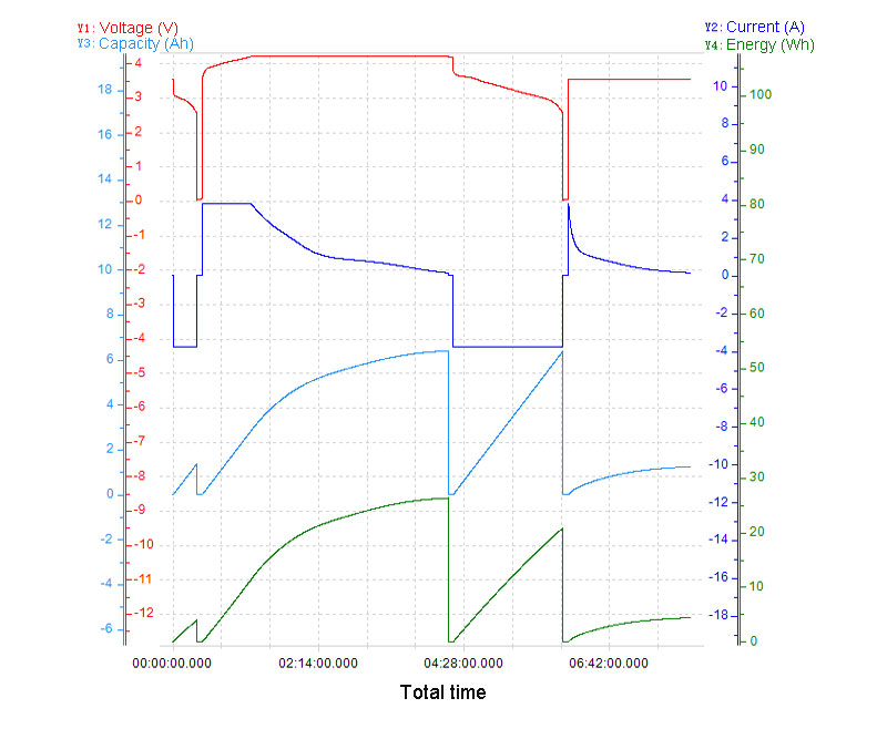
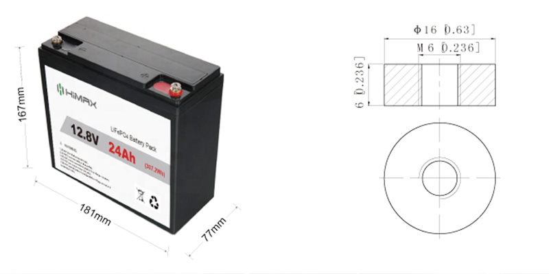
- Nominal voltage: 12.8V | Nominal capacity: 24Ah | Energy: approx. 307Wh
- Cycle life: >2,000 cycles at 0.2C, 100% depth of discharge
- Self-discharge: under 3% per month
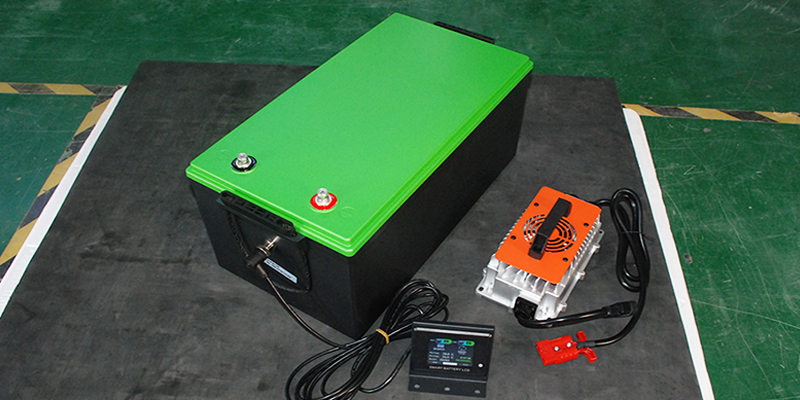
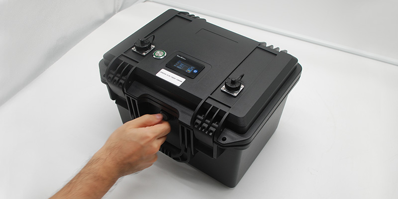
- Case: ABS plastic, IP65-rated | Approx. dimensions: 181 x 77 x 167mm | Approx. weight: 3kg
- Discharge temperature range: -20°C to 60°C | Charge temperature range: 0°C to 55°C
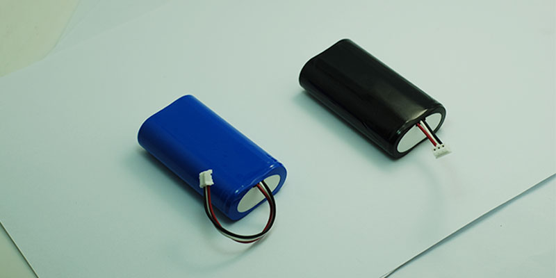
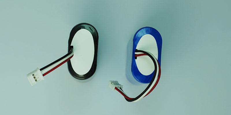
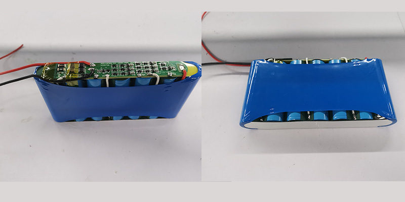
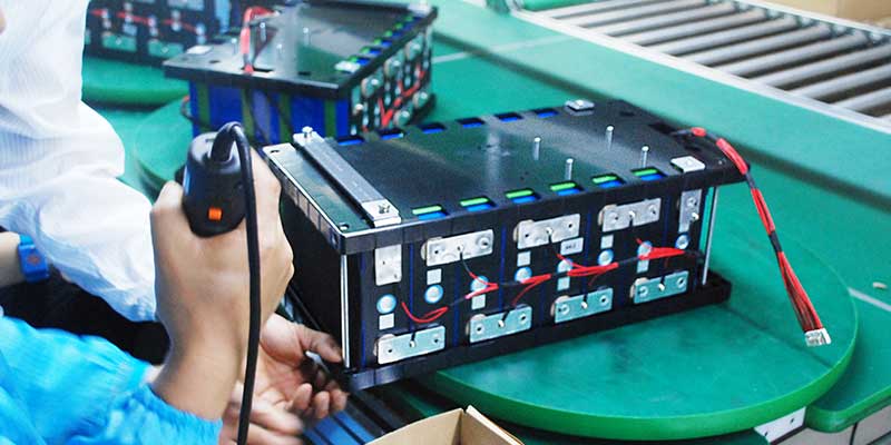
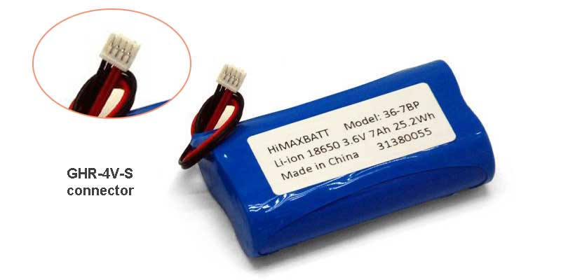
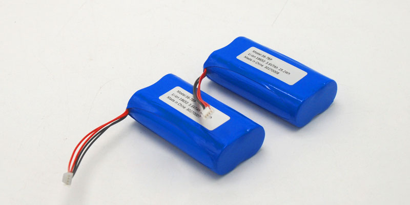
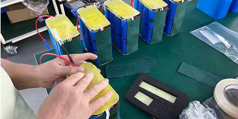
4S 18650 LiFePO4 cell groups with BMS boards during assembly of a 12.8V battery pack platform used in solar-powered outdoor lighting.
BMS Protection: The Engineering Behind the Safety Margin
The battery management system (BMS) is where much of the real engineering work occurs. A properly integrated BMS monitors every cell for overcharge, over-discharge, overcurrent, and short circuit conditions. In addition, it adds temperature protection, cutting off charge or discharge before a fault becomes a safety event. For an unattended outdoor product, this layer of protection enables the fixture to operate safely for years without supervision.
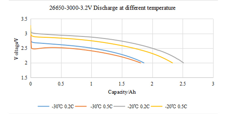
Thermal Management for Charge and Discharge Across Seasons
Charge and discharge behavior both shift with temperature, and a pack that isn’t managed for that will lose capacity or wear out early in a hot summer or a cold winter. Setting charge voltage, current limits, and cutoff thresholds to match the cell’s real behavior across its full temperature range is standard practice for a pack meant to sit outdoors year-round, rather than something added after the fact.
Compliance You Can Verify: MSDS and Spec Sheet
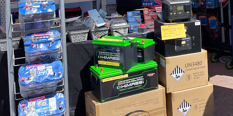
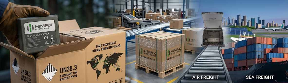
For OEM buyers and safety officers, documentation matters as much as performance. Every 12.8V 24Ah LiFePO4 battery pack we ship is backed by a full Material Safety Data Sheet detailing cell composition, handling precautions, and transport classification under UN3480/UN3481, along with a complete technical specification sheet covering electrical, environmental, and mechanical performance.
Download the battery MSDS or the 12.8V 24Ah LiFePO4 spec sheet directly, or contact our team for the latest revision for your project.
From Spec to Supply: Custom Engineering for OEM Lighting Brands
Most lighting OEMs don’t need a battery off a shelf — they need one engineered around their driver board’s voltage window, their fixture’s internal dimensions, and their target market’s certification requirements. That’s where BMS integration, thermal management, and pack customization come together: adjusting capacity, connector type, wire length, case dimensions, and protection thresholds to fit the product, not the other way around. The goal is a battery that disappears into the design instead of dictating it.
Where This Battery Platform Also Powers Other Products
The same 12.8V LiFePO4 platform used in solar garden lights also supports other lighting battery applications, from path and landscape lighting to standalone solar garden light battery systems built for OEM production. Across all of them, the design priorities stay the same: safe chemistry, verified compliance, and a pack that performs outdoors, unattended, for years.
Talk to Our Power System Design Team
If you’re specifying a battery for solar garden lights or another outdoor lighting product, our engineering team can review your driver requirements, enclosure space, and target climate, then recommend a cell and BMS configuration to match. Contact HIMAX Electronics to start the conversation.
About the Author
Shawn — Battery Engineer, Power System Design, HIMAX Electronics. With over 10 years of experience in lithium battery system design, Shawn specializes in Li-ion, LiFePO4, and LiPo battery packs. His expertise includes BMS integration, thermal management, and custom power solutions for medical and consumer devices.