Commercial Disclosure: The HiMAXBATT Editorial Team brings together expertise in lithium battery manufacturing, battery engineering, power systems, and global application support to provide practical, technically informed content for businesses and industry professionals. Our content covers lithium-ion and LiFePO4 batteries, custom battery packs, BMS technology, charging solutions, battery selection, industrial applications, product updates, and HiMAXBATT news. All content reflects HiMAXBATT’s official editorial perspective and our commitment to delivering safe, reliable, and application-focused lithium battery solutions to customers worldwide.

Key Takeaways

  • GPS tracker battery life depends on sleep current, positioning frequency, upload frequency, network signal quality, temperature, and battery self-discharge.
  • One of the most effective ways to extend runtime in low-power devices is to reduce unnecessary wake-ups, positioning events, and communication sessions.
  • Low average power consumption does not necessarily mean low pulse-current requirements.
  • Cellular modules can draw high current for short periods when transmitting data, so both the battery and the power supply circuit must be able to support these peaks.
  • Primary lithium batteries are well suited for low-frequency communication and long-term unattended devices, while rechargeable lithium batteries are a better fit for devices that can be recharged periodically or powered by solar energy.
  • Long-life IoT devices should pay close attention to battery self-discharge, BMS quiescent current, and standby power consumption from power converters.
  • Low temperatures can reduce usable capacity and peak output capability, while high temperatures can accelerate battery aging.
  • Accurate runtime estimates require measuring total device power consumption under realistic temperatures, network conditions, and operating frequencies.

Introduction

GPS trackers, asset tracking tags, smart meters, environmental sensors, and remote monitoring terminals often need to operate unattended for months or even years. For these low-power devices, the battery affects more than runtime. It can also influence device size, communication stability, positioning success rate, and long-term maintenance costs.

Many IoT devices consume very little power while sleeping, but GPS positioning, cellular network connection, data transmission, and firmware updates can create relatively high current peaks. If a battery is selected only by average power consumption or rated capacity, the device may disconnect, restart, or fail to upload data even when some battery capacity still remains.

This article explains how to extend battery life in GPS trackers and IoT devices by looking at battery capacity, peak current, positioning and communication frequency, sleep current, ambient temperature, and power management.

Why Do GPS Trackers and IoT Devices Run Out of Power Earlier Than Expected?

A GPS tracker typically needs to perform several tasks, including sensor acquisition, satellite positioning, data processing, network connection, and data transmission. A typical operating cycle may include:

  1. The microcontroller wakes from sleep mode;
  2. Temperature, motion, or other sensors are read;
  3. The GPS, BeiDou, or GNSS module is activated;
  4. The device searches for satellites and calculates its position;
  5. The NB-IoT, LTE-M, 4G, or other communication module is activated;
  6. The device registers with the network and establishes a connection;
  7. Location, status, and alarm data are uploaded;
  8. Logs are saved and the device returns to sleep mode.

When satellite and cellular signals are strong, these steps can be completed relatively quickly. If the device is located in an underground parking garage, inside a shipping container, between buildings, or in a remote area, positioning and network registration may take longer and require multiple retries, which can significantly increase energy consumption.

Another commonly overlooked issue is sleep-mode power consumption. Power LEDs, sensors, resistor dividers, communication modules, fuel gauges, and power-management ICs may each draw only a small amount of current, but over months or years, these continuous loads can meaningfully reduce battery life.

How Do You Calculate GPS Tracker Battery Life?

Power consumption in low-power devices can vary significantly between operating states, so each state should be calculated separately.

Energy Used per Operating Cycle (mAh) = Sum of Current in Each State (mA) × Time in That State (h)

Theoretical Battery Life (days) ≈ Usable Battery Capacity (mAh) ÷ Daily Energy Consumption (mAh)

Assume a battery with a rated capacity of 5000mAh and an estimated usable capacity of 80%:

5000 × 80% ÷ 23.13 ≈ 173 days

Under these assumptions, the theoretical battery life would be approximately 5.7 months. Actual performance will also be affected by battery self-discharge, temperature, aging, power-conversion efficiency, and network retries.

Any example power-consumption values should be used only to illustrate the calculation method. Actual consumption can vary significantly depending on the chipset, antenna, communication network, and software strategy. Final battery selection should be based on measurements from the complete device.

Why Can’t You Just Divide Battery Capacity by Average Current?

Dividing capacity by average current can be useful for an initial estimate, but it can overlook several important variables:

  • Rated battery capacity is measured under specific discharge-current and temperature conditions;
  • Battery self-discharge consumes part of the available capacity;
  • DC-DC converters introduce efficiency losses;
  • The BMS, fuel gauge, and protection circuits consume power continuously;
  • Low temperatures can reduce usable capacity;
  • Communication current peaks can cause voltage drop;
  • Battery internal resistance increases with aging;
  • Failed network connections may trigger repeated retries;
  • The device may reach its minimum operating voltage before the battery is fully discharged.

For this reason, GPS tracker battery sizing should include a reasonable design margin. For IoT devices expected to operate for several years, self-discharge and microamp-level standby current are especially important.

How Does GPS Positioning Frequency Affect Battery Life?

Positioning frequency is often one of the most important factors affecting GPS tracker battery life. A device that acquires a position every minute can have very different runtime from one that reports only once per day.

Positioning and Upload Strategy Impact on Battery Life Typical Applications
Continuous positioning and real-time uploads Highest power consumption Real-time vehicle tracking, emergency applications
Positioning every 5–15 minutes Relatively high power consumption Logistics, mobile asset management
Hourly positioning Lower power consumption General equipment and cargo tracking
Positioning several times per day Can significantly extend runtime Low-frequency asset inventory
Positioning only when moving Reduces power use while stationary Containers, tools, and equipment management
Event-triggered positioning Low normal operating power Anti-theft and geofence alerts
Batched data uploads Reduces the number of network connections Environmental monitoring, non-real-time data collection

If real-time location is not required, a “motion-triggered + scheduled reporting” strategy can be effective. The device can remain in deep sleep while stationary, increase positioning and upload frequency when movement is detected, and return to low-power mode once the device becomes stationary again.

How Can You Reduce GNSS Positioning Power Consumption?

GPS, BeiDou, and other GNSS modules need to search for satellites and calculate a position after startup. The longer the time to first fix, the more energy is usually consumed.

Common optimization methods include:

  • Retaining valid time, position, and ephemeris data;
  • Using assisted positioning or hot starts;
  • Optimizing GNSS antenna placement and RF matching;
  • Reducing antenna blockage from metal housings and internal structures;
  • Reducing unnecessary positioning attempts indoors;
  • Adjusting positioning intervals based on motion state;
  • Setting a reasonable positioning timeout;
  • Fully powering down the module when positioning is not needed.

A shorter timeout does not always save energy. If the timeout is too short, the device may repeatedly start, fail, and retry, which can increase total power consumption. The timeout should balance positioning success rate with energy use for the intended application.

How Do Different IoT Communication Methods Affect Battery Life?

Communication Method Main Characteristics Key Battery Considerations
NB-IoT Suitable for small data packets and infrequent reporting Network registration, PSM settings, and peak current
LTE-M Supports mobility and relatively low latency Online duration, coverage, and transmission frequency
4G Cellular Mature coverage and higher data capability Peak current and retries in weak-signal areas
LoRa/LoRaWAN Suitable for long-range, low-data applications Gateway coverage, transmit power, and reporting frequency
Bluetooth Low Energy Short-range and low-power Advertising interval and connection frequency
Wi-Fi High data rate and easy network access Scanning, connection, and always-on power consumption
Satellite Communication Suitable for areas without cellular coverage Transmit power, antenna performance, and transmission duration

In weak-signal environments, cellular modules may increase transmit power and repeatedly search for or register with the network. Product validation should not be limited to a strong-signal laboratory environment. Testing should also cover real-world conditions such as underground parking garages, cargo compartments, shipping containers, and remote areas.

Why Can Peak Current Cause a Tracker to Shut Down Early?

When a communication module transmits data, current demand can rise sharply for a short period. Even if the battery still has remaining capacity, high battery internal resistance or excessive circuit impedance can cause the output voltage to drop quickly.

If voltage falls below the minimum operating requirement of the module or power-management circuit, the device may experience:

  • Unexpected restarts;
  • Network registration failures;
  • Position data upload failures;
  • BMS undervoltage protection;
  • Repeated wake-up and retry cycles;
  • Inability to use the remaining battery capacity effectively;
  • Premature low-battery warnings.

These problems can become more severe at low temperatures, at low state of charge, and as the battery ages. Possible solutions include selecting cells with stronger pulse-current capability, shortening the power path, reducing connection resistance, optimizing the DC-DC converter, and adding suitable buffer capacitors.

Capacitors can help absorb short current spikes, but they cannot replace proper battery selection. If the pulse lasts longer, the battery must still provide sufficient output current.

How Can You Actually Reduce Sleep Current in IoT Devices?

For devices designed to operate for years, even an additional few tens of microamps of continuous current can consume a meaningful amount of energy. When reducing sleep current, check:

  • Whether the MCU enters its lowest-power mode;
  • Whether the GNSS module is truly powered off;
  • Whether the communication module continues searching for a network;
  • Whether sensors continue sampling unnecessarily;
  • Whether indicator LEDs remain on;
  • The quiescent current of power-management ICs;
  • Whether resistor dividers consume current continuously;
  • The standby current of the BMS and fuel gauge;
  • Whether unused interfaces are left in abnormal states;
  • Whether debugging circuits remain connected;
  • Whether unexpected wake-up events are occurring.

A standard multimeter may not capture the rapid transition from microamp-level sleep current to large communication pulses. During development, the full current waveform should be recorded and the actual energy consumed during each task cycle should be measured.

How Can Communication and Software Strategies Be Optimized?

Wireless communication is often one of the largest energy consumers in IoT devices. Power consumption can be reduced by:

  1. Combining multiple data points and uploading them in batches;
  2. Reporting only when data changes beyond a defined threshold;
  3. Reducing unnecessary server handshakes;
  4. Compressing location and sensor data;
  5. Returning to sleep as soon as transmission is complete;
  6. Using power-saving mechanisms such as PSM and eDRX appropriately;
  7. Gradually increasing retry intervals after network failures;
  8. Adjusting the upload schedule based on signal strength;
  9. Performing firmware updates when SOC is high or external power is available;
  10. Avoiding continuous high-frequency network searches in areas with no coverage.

When each transmission contains only a small amount of data, the energy used for network registration and connection setup may exceed the energy used to send the data itself. For this reason, moderate batch uploading can often be more energy-efficient than frequently transmitting small data packets.

How Does Temperature Affect GPS Tracker Batteries?

Low-Temperature Conditions

Cold-chain logistics, winter outdoor use, and high-altitude applications can reduce battery usable capacity and pulse-output capability. Communication peaks may also cause greater voltage drop. Rechargeable lithium batteries require appropriate charging limits or protection strategies at low temperatures.

High-Temperature Conditions

Trackers installed on vehicle dashboards, roofs, outside shipping containers, or in direct sunlight may experience internal temperatures significantly higher than the surrounding air temperature. Prolonged exposure to heat can accelerate battery aging and self-discharge while also reducing the life of connectors, seals, and electronic components.

Temperature Cycling and Condensation

When equipment operates in environments with large day-to-night temperature swings, or moves from cold storage into a warm and humid area, condensation may form inside the enclosure. Product design should consider enclosure protection, connector sealing, PCB protection, and pressure equalization.

What Functions Should the BMS and Power Management System Provide?

A BMS used in rechargeable GPS trackers and IoT devices typically needs to support:

  • Overcharge and over-discharge protection;
  • Charge and discharge overcurrent protection;
  • External short-circuit protection;
  • High- and low-temperature protection;
  • Battery voltage, current, and temperature monitoring;
  • State-of-charge (SOC) estimation;
  • Charge and discharge control;
  • Fault logging;
  • Communication functions when required.

For low-power devices, the BMS’s own quiescent current is especially important. If the protection circuit continuously draws too much current, it can offset the benefits of a low-power device design.

Primary-battery devices usually do not need a conventional charging-management BMS, but they may still require overcurrent protection, reverse-polarity protection, battery measurement, and power isolation.

Can Solar Power Make IoT Devices Maintenance-Free?

Solar power can recharge container trackers, livestock trackers, field environmental sensors, and remote monitoring terminals, but it does not mean the device will operate indefinitely without maintenance.

A solar-powered battery system should consider:

  • The device’s actual daily energy consumption;
  • Solar availability during the worst month at the project location;
  • Solar panel power and installation angle;
  • Dust, snow, and shading;
  • Backup capacity for consecutive cloudy or rainy days;
  • Charge controller quiescent current;
  • Charging capability at high and low temperatures;
  • Battery capacity degradation after long-term cycling.

The solar panel must supply not only the device’s current-day energy demand but also enough energy to replenish the battery after periods of poor weather. Solar panel size and battery capacity should therefore be calculated together.

How Do You Test the Real Battery Life of a GPS Tracker?

Complete Operating Cycle Testing

Measure the complete current waveform from sleep, wake-up, positioning, network connection, and data upload through the return to sleep mode. Use this data to calculate the actual energy consumed by one complete task cycle.

Pulse Load Testing

Simulate the communication module’s peak current and verify battery voltage, DC-DC output, and whether the device restarts.

High- and Low-Temperature Testing

Test positioning, communication, charging, and runtime across the product’s specified temperature range, with particular attention to voltage drop at low temperatures.

Weak-Signal Testing

Test positioning time, network registration time, and retry count under poor satellite and cellular signal conditions.

Long-Term Standby Testing

Measure the device’s true sleep current, battery self-discharge, and any unexpected software wake-up events.

Aged-Battery Testing

Retest peak power and runtime using batteries that have undergone cycling or storage aging to confirm that the device can still complete critical tasks near end of life.

How Do You Choose a Battery Supplier for GPS Trackers and IoT Devices?

A battery supplier for low-power device projects should be able to select cells based on actual power demand and operating environment, not simply provide a rated capacity.

Key capabilities to evaluate include:

  • Ability to analyze complete-device current waveforms;
  • Support for both primary and rechargeable lithium battery solutions;
  • Ability to evaluate continuous and pulse-current requirements;
  • Support for low-quiescent-current protection designs;
  • Custom voltage, capacity, and mechanical dimensions;
  • Custom connectors, wire harnesses, and communication functions;
  • Cell and battery-pack traceability;
  • Temperature, cycle-life, and reliability test data;
  • Support for transportation testing and target-market requirements;
  • Stable mass-production capability and engineering change management.

GPS Tracker Battery Selection Checklist

When requesting a custom battery solution from a battery manufacturer, prepare the following information:

  1. Device type and specific application;
  2. Target battery life;
  3. Sleep, positioning, processing, and communication current;
  4. Peak current and pulse duration;
  5. Number of positioning and data-upload events per day;
  6. Communication network and module model;
  7. Minimum and maximum device operating voltage;
  8. Available battery space and weight limits;
  9. Operating, charging, and storage temperatures;
  10. Primary or rechargeable battery requirement;
  11. USB, vehicle power, or solar charging method;
  12. Water resistance, dust resistance, vibration resistance, and tamper resistance requirements;
  13. Connector, wire harness, and enclosure requirements;
  14. Expected product service life;
  15. Transportation testing, certification, and target-market requirements;
  16. Sample quantity, mass-production volume, and delivery schedule.

Frequently Asked Questions (FAQ)

How Long Does a GPS Tracker Battery Usually Last?

GPS tracker battery life can range from a few days to several years. Actual runtime depends on battery energy, positioning frequency, upload frequency, network signal quality, sleep current, ambient temperature, and whether the device is moving.

Why Doesn’t a 5000mAh Battery Last as Long as Expected?

Common causes include frequent communication, retries in weak-signal areas, low temperatures, power-conversion losses, excessive sleep current, battery self-discharge, and voltage drop caused by peak current that forces the device to shut down early.

Does Lower Positioning Frequency Always Extend Battery Life?

Usually, but not always. The result also depends on the energy consumed during each positioning and communication event. If each wake-up involves a long satellite search or repeated network registration attempts, even infrequent operation can consume significant energy.

Can a Primary Lithium Battery Power an IoT Device for 10 Years?

Some ultra-low-power applications may be designed for multi-year operation, but battery self-discharge, device standby current, ambient temperature, pulse-current demand, and end-of-life voltage must all be considered. Long-term modeling and real-world validation are still required.

Why Does a Cellular Module Cause the Device to Restart at Startup?

When the communication module transmits data, it may draw a relatively large peak current. If the battery cannot support the pulse, the power path has too much resistance, or the power-conversion design is inadequate, the input voltage may drop rapidly and restart the system.

Can Adding a Capacitor Solve an Insufficient Peak-Current Problem?

A properly selected capacitor can reduce the impact of short current spikes, but it cannot replace correct battery selection. If the pulse lasts longer, the battery must still provide sufficient output current.

How Should You Choose a Battery for a GPS Tracker Used in Low Temperatures?

Focus on usable capacity, pulse-current capability, and output voltage at low temperatures. Rechargeable devices should also include low-temperature charging protection. Low-temperature cells, insulation, or heating may be considered when necessary.

How Can NB-IoT Devices Reduce Power Consumption?

Power consumption can be reduced by optimizing PSM and eDRX settings, lowering reporting frequency, batching data, reducing network-search time, and entering sleep mode promptly after transmission. These parameters should be validated on the actual network.

Why Does the Remaining Battery Percentage Suddenly Drop?

The SOC algorithm may be inaccurate, or low temperature, peak load, or battery aging may cause a temporary voltage drop. Current waveforms, temperature, internal resistance, and fuel-gauge settings should be evaluated together.

How Should a GPS Tracker Be Stored When It Is Not Used for a Long Time?

Rechargeable batteries should be stored at an appropriate state of charge according to the manufacturer’s recommendations and kept in a dry environment within the recommended temperature range. Unnecessary loads should be disabled before storage, and battery condition should be checked periodically.

Can Solar Charging Keep a Tracker Online Permanently?

Solar charging can extend runtime, but actual performance depends on available sunlight, shading, panel power, controller losses, and battery aging. The system still needs enough backup energy for consecutive cloudy or rainy days and should be inspected periodically.

How Do You Know Whether the Battery Has Enough Design Margin?

Build an energy model based on daily consumption, target operating life, usable-capacity ratio, temperature, aging, and self-discharge. Then validate the complete device under worst-case conditions such as weak network signals and low temperatures.

About Himax Electronics

Himax Electronics specializes in custom battery and power solutions for complex applications worldwide. For GPS trackers, asset tracking terminals, smart sensors, remote monitoring equipment, and other low-power IoT devices, we can develop application-specific lithium-ion battery packs, power supplies, chargers, and accessories based on sleep current, positioning frequency, communication peaks, target runtime, installation space, and operating temperature.

From battery chemistry, voltage, and capacity selection to low-quiescent-current protection, BMS design, wire harnesses, connectors, and charging-system integration, Himax Electronics works with customers to develop products designed for longer runtime, stable operation, and easier system integration.

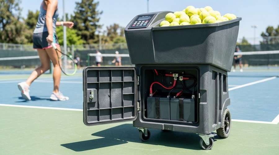
Tennis ball machine with high-performance battery pack on court

Commercial Disclosure: The Himax Electronics Editorial Team brings together expertise in battery products, power technologies, engineering applications, and global customer support to share practical information about battery technology, custom battery solutions, and power applications. Our content covers lithium-ion batteries, LiFePO4 batteries, battery pack design and selection, charging and power solutions, industry application guides, product updates, and official Himax Electronics news. Our goal is to help engineers, procurement professionals, and businesses better understand battery technologies and make informed decisions based on their specific application requirements. All content reflects the official editorial perspective of Himax Electronics and our commitment to providing reliable, flexible, and professional custom battery and power solutions for complex applications worldwide.

Key Takeaways

  • Before choosing a battery for a tennis ball machine, confirm the system voltage, continuous power consumption, startup current, and desired training time.
  • Lead-acid batteries generally have a lower upfront cost and may be suitable for some existing 12V or 24V systems designed around lead-acid batteries.
  • LiFePO4 batteries typically offer higher energy density, which can help reduce equipment weight and make them well suited for applications involving frequent charge-discharge cycles.
  • Even at the same rated capacity, lead-acid and LiFePO4 batteries can differ in usable energy, discharge-voltage characteristics, and long-term capacity degradation.
  • When replacing a lead-acid battery with LiFePO4, verify charger compatibility, operating voltage range, low-voltage protection thresholds, and installation dimensions.
  • When purchasing batteries, request cell specifications, BMS protection logic, discharge curves, cycle-test data, and transportation documentation.

Introduction

The battery in a tennis ball machine can affect portability, continuous training time, ball-launching consistency, and long-term maintenance costs. Whether the machine is used for daily club training, coaching sessions, school programs, or individual practice, battery selection should not be based on Ah alone. Motor startup and continuous ball feeding can create pulsed loads, while outdoor heat, long periods of storage, frequent charging, and repeated transportation around the court can also affect battery performance.

Lead-acid and LiFePO4 batteries are two common options for tennis ball machines. Neither chemistry is universally better for every application. A more practical approach is to evaluate system voltage, load profile, usage frequency, machine design, charger compatibility, and long-term budget together.

Why Shouldn’t You Choose a Tennis Ball Machine Battery Based on Ah Alone?

Ah, or amp-hours, describes a battery’s charge capacity under specified conditions, but it does not fully indicate how long a tennis ball machine will operate. Motor loads can change when the machine starts, feeds balls, adjusts ball speed, changes oscillation patterns, or raises and lowers the ball trajectory. Machines with remote controls, displays, or smart training programs may also have additional electronic power consumption.

A more useful metric for comparing stored energy is Wh, or watt-hours:

Battery Energy (Wh) = Nominal Voltage (V) × Rated Capacity (Ah)

For example, a 12V 50Ah battery has a theoretical energy capacity of approximately 600Wh. A 24V 25Ah battery also provides approximately 600Wh. Although their stored energy is similar, their operating voltages, wiring requirements, and controller compatibility are different, so they cannot simply be interchanged.

Estimated runtime can be calculated using:

Estimated Runtime ≈ Usable Battery Energy (Wh) ÷ Average Tennis Ball Machine Power Consumption (W)

“Usable battery energy” should also account for depth of discharge, temperature, battery ageing, motor peak current, and controller efficiency. For training equipment, real-world machine testing is recommended when establishing final runtime specifications.


Tennis ball machine battery compartment on court


Factor Affecting Runtime Effect on the Tennis Ball Machine What to Verify When Purchasing
Ball speed and feed rate Changes motor duty cycle and power consumption Power consumption under different training modes
Motor startup current Startup or acceleration may create short high-current demands Peak current, wiring, and fuse specifications
Battery temperature Low temperatures can reduce discharge capability, while high temperatures can affect battery life Charge and discharge temperature ranges
Battery ageing Usable capacity changes over time Cycle life and capacity-retention data
Controller efficiency Motor drives and DC-DC conversion introduce energy losses Overall system efficiency or measured runtime
Training duration Different continuous operating times require different battery configurations Session length and daily usage frequency

Lead-Acid vs. LiFePO4 Batteries for Tennis Ball Machines

Comparison Lead-Acid Battery LiFePO4 Battery
Upfront cost Generally easier to keep initial costs low Typically higher than a comparable lead-acid solution
Weight and size Usually heavier and larger for the same amount of stored energy Can help reduce equipment weight for a similar amount of stored energy
Usable capacity range Depth of discharge is often limited to help preserve battery life A wider portion of rated capacity may be usable with appropriate BMS management
Frequent cycling May be suitable for lower-frequency use or float-service applications Well suited for frequent training and repeated cycling
Discharge voltage Terminal voltage tends to change more noticeably as the battery discharges Relatively stable discharge voltage, but protection cutoff thresholds still matter
Maintenance considerations Requires attention to long-term storage, undercharging, and storage conditions Requires proper BMS operation, charger compatibility, and low-temperature charging protection
Replacement compatibility Commonly compatible with charging systems in many existing machines Charger logic and system voltage range should be verified before replacement
Portability Battery weight may be noticeable when moving the machine Can help reduce the effort required to move equipment around the court

U.S. Department of Energy energy-storage information notes that conventional lead-acid technology generally has a lower upfront cost, while differences exist between lead-acid and lithium-ion technologies in areas such as energy density, cycle life, and deep-discharge performance. Total lifecycle cost should therefore be evaluated according to the actual operating conditions. U.S. Department of Energy Energy Storage Technology and Cost Information

When Should You Consider a Lead-Acid Battery?

Lead-acid batteries still have a place in tennis ball machine applications. For example, a valve-regulated lead-acid battery may be worth considering when the machine is used infrequently, the existing charger is designed around a lead-acid charging profile, there is sufficient battery-compartment space, and minimizing upfront cost is a priority.

However, lead-acid batteries should not be stored in a deeply discharged state for extended periods. Capacity can be affected when a tennis ball machine is left unused during the off-season, goes for long periods without charging, or regularly experiences deep discharge.

When purchasing a battery, determine whether it is designed primarily for starting or deep-cycle applications. Tennis ball machines should be matched to batteries appropriate for repeated cycling rather than automatically using a battery intended primarily for short bursts of high starting current.

When Should You Consider a LiFePO4 Battery?

LiFePO4 batteries can be a good fit for tennis ball machines where equipment weight, repeated cycling, and usable battery capacity are important. For coaches, tennis academies, and frequently used court equipment, batteries may go through repeated charge-discharge cycles, making cycle performance and charging efficiency important operational considerations.

However, upgrading from lead-acid to LiFePO4 is not as simple as replacing a “12V lead-acid battery” with a “12V lithium battery.” Common 12V LiFePO4 batteries use multiple cells connected in series, and their full-charge voltage, discharge cutoff voltage, and charging profile differ from those of lead-acid batteries. If the machine’s original charger uses a long-term float-charging strategy that is not appropriate for the lithium battery, it may not work properly with the battery management system.


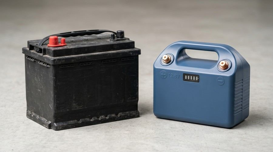
Comparison between 12V lead-acid battery and 12V LiFePO4 battery pack


For lithium batteries used in industrial and motive auxiliary applications, the safety requirements and test approaches covered by IEC 62619:2022 may provide a useful reference. This standard does not replace product-specific testing, but it can be considered during supplier quality reviews and technical discussions.

What Should You Check Before Replacing a Lead-Acid Tennis Ball Machine Battery With LiFePO4?

Item to Check What to Confirm Potential Issue
Nominal voltage Whether the original machine uses a 12V, 24V, or another voltage system Incorrect voltage may cause controller problems
Full-charge voltage Allowable input-voltage range of the controller and motor driver Full-charge voltage may trigger overvoltage protection
Low-voltage protection Original equipment shutdown threshold and lithium BMS cutoff point The machine may shut down early or the BMS may disconnect
Charger parameters Constant-current and constant-voltage settings and whether long-term float charging is used Battery may not fully charge or the charging profile may be unsuitable
Peak current Instantaneous current during motor startup and high-frequency ball feeding BMS overcurrent protection may be triggered
Battery compartment dimensions Length, width, height, terminal orientation, and mounting method Installation problems or vibration-related loosening
Communication and display Whether a battery gauge, CAN, RS485, or Bluetooth is required Original battery-level indicator may become inaccurate

What Should Tennis Ball Machine Battery Design Consider From a Manufacturer’s Perspective?

Cell and BMS Matching

The performance of a LiFePO4 battery pack depends on the interaction between the cells, BMS, wiring, connectors, fuses, and mechanical components. The BMS should be matched to the motor’s peak-current requirements and provide appropriate overcharge, over-discharge, overcurrent, short-circuit, and temperature protection.

For tennis ball machines requiring faster charging, the allowable cell charging rate and charger power should also be evaluated.

Vibration and Drop Protection

Tennis ball machines may be moved across hard courts, gravel paths, or transported in vehicle trunks, exposing the battery pack to vibration and impact. Secure mounting brackets, flame-retardant insulation materials, anti-loosening terminal designs, and strain relief for wiring can help reduce the risk of loose electrical connections.


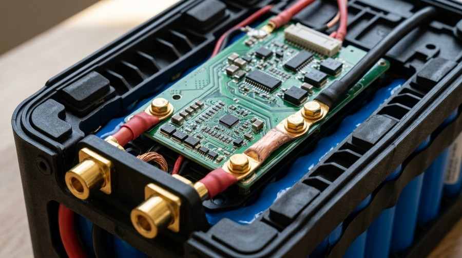
LiFePO4 battery BMS protection circuit board and interior design


The battery compartment should also prevent metallic foreign objects from entering and potentially shorting the terminals.

Temperature and Storage Management

Tennis courts can become hot during summer, while winter or outdoor use may expose batteries to low temperatures. High temperatures can accelerate battery ageing, while low temperatures may reduce discharge capability.

For equipment stored for extended periods, follow the battery supplier’s recommendations for state of charge, storage temperature, and recharge intervals. Batteries should not remain deeply discharged for long periods.

Charging Interface and User Experience

Tennis ball machines are often operated by nontechnical users, so charging-connector design, charge-status indicators, fault warnings, and battery-level displays can affect the overall user experience.

For removable batteries, connector mating-cycle life, terminal plating, water resistance, and locking mechanisms should also be evaluated to help prevent poor electrical contact during operation.

Common Questions About Tennis Ball Machine Batteries

What Battery Capacity Does a Tennis Ball Machine Need?

Battery capacity should be calculated based on system voltage, average power consumption, training duration, and peak current. Ideally, collect power-consumption data under different ball speeds, oscillation modes, and feed rates, then account for temperature and ageing margins when determining the required capacity.

Selecting a battery based only on machine weight or available battery-compartment space may result in inadequate runtime.

Can You Replace a 12V 50Ah Lead-Acid Battery With a 12V 50Ah LiFePO4 Battery?

The same capacity rating does not mean the batteries are directly interchangeable. Full-charge voltage, low-voltage protection thresholds, charger output, motor peak current, battery-compartment dimensions, and terminal orientation should all be verified.

After these factors have been checked, prototype testing should be performed before the replacement is finalized.

Can a LiFePO4 Battery Make a Tennis Ball Machine Lighter?

For a similar amount of usable energy, LiFePO4 batteries can generally help reduce battery weight. However, the total reduction in machine weight also depends on the motors, frame, ball hopper, wheels, and battery mounting structure.

Can a Lead-Acid Battery Be Damaged by Long-Term Storage?

Storing a lead-acid battery in a deeply discharged state for an extended period can affect its capacity and service life. When a tennis ball machine is stored during the off-season, the battery should be recharged and inspected according to the supplier’s recommendations and kept away from excessive heat, moisture, and prolonged direct sunlight.

Does a Lithium Battery for a Tennis Ball Machine Need a BMS?

LiFePO4 battery packs typically require a BMS to monitor individual cell voltage, temperature, and current and to provide protection or fault warnings. The BMS’s continuous-current and peak-current capabilities should be matched to the equipment’s load profile.

About Himax Electronics

Himax Electronics specializes in custom battery and power solutions for demanding applications worldwide, including proprietary lithium-ion battery packs, power supplies, chargers, and accessories. For tennis ball machines, training equipment, outdoor sports equipment, and other mobile devices, Himax Electronics can help customers evaluate lead-acid and LiFePO4 battery solutions based on system voltage, peak current, required training time, available installation space, operating temperature, and charging requirements, while providing customized support for project development and delivery.

High-tech AI ski goggles resting on alpine snow background

Commercial Disclosure: The Himax Electronics Editorial Team brings together expertise in battery products, power technologies, engineering applications, and global customer support to share practical information about battery technology, custom battery solutions, and power applications. Our content covers lithium-ion batteries, LiFePO4 batteries, battery pack design and selection, charging and power solutions, industry application guides, product updates, and official Himax Electronics news. Our goal is to help engineers, procurement professionals, and businesses better understand battery technologies and make informed decisions based on their specific application requirements. All content reflects the official editorial perspective of Himax Electronics and our commitment to providing reliable, flexible, and professional custom battery and power solutions for complex applications worldwide.

Key Takeaways

  • Cold temperatures can reduce the usable capacity and discharge power of lithium-ion batteries, so the real-world runtime of AI ski goggles may be shorter than their room-temperature ratings.
  • Displays, cameras, AI processors, wireless connectivity, and heated anti-fog features create dynamic loads, so energy consumption should be estimated based on actual usage patterns.
  • Low-temperature charging requires careful management. Cell temperature, charging current, and BMS limits should be coordinated.
  • Battery packs need to balance low weight, comfortable weight distribution, water resistance, condensation protection, impact resistance, and thermal management rather than simply maximizing capacity.
  • Low-temperature performance depends on factors such as cell chemistry, electrolyte formulation, electrode design, packaging, and software control strategies.
  • During sourcing or product development, suppliers should provide discharge curves, cycle-test data, and protection-logic documentation under the target temperature and load conditions.

Introduction

AI ski goggles integrate features such as displays, cameras, motion sensors, voice interaction, Bluetooth, positioning, communications, and image processing. The battery not only determines how long the device can operate but can also affect startup, display performance, recording, and connection stability on the slopes. Low temperatures, wind chill, snow and moisture, and frequent transitions between indoor and outdoor environments can expose the battery system to more demanding conditions than typical consumer electronics.

For brands and product development teams, a low-temperature battery solution should not be designed around rated capacity alone. Cell chemistry, load profiles, insulation, BMS strategies, charging limitations, and overall device protection should all be evaluated together.

Why Does Cold Weather Reduce AI Ski Goggle Battery Runtime?

Li-ion batteries rely on lithium ions moving between the positive and negative electrodes during charging and discharging. As temperature drops, electrolyte viscosity can increase, ion transport becomes more difficult, and battery internal resistance can change. As a result, the battery may experience earlier voltage drop, limited power output, or low-battery protection under cold conditions.

Research from the U.S. National Renewable Energy Laboratory (NREL) indicates that low temperatures can reduce lithium-ion battery capacity and power performance while increasing internal resistance. The extent of these effects depends on factors such as battery chemistry, load current, and temperature conditions. NREL Research on Low-Temperature Lithium-Ion Battery Performance

AI ski goggles differ from simpler devices such as Bluetooth earbuds or fitness trackers because their loads can fluctuate significantly. Power consumption may increase when users activate 4K video recording, AR prompts, navigation, real-time translation, slope recognition, or anti-fog heating. If the battery is already cold, the resulting voltage drop may become more pronounced under these higher loads.

Cold-Weather Factor Potential Effect on AI Ski Goggles Design or Sourcing Consideration
Increased battery internal resistance Faster voltage drop under high loads and possible protection triggering Review low-temperature discharge curves and pulse-discharge capability
Reduced usable capacity Shorter actual recording, display, and communication time Estimate runtime using capacity data at the target temperature
Limited peak output Simultaneous camera, display, and AI processing loads may cause lag or restarts Evaluate peak current, wiring voltage drop, and BMS current limits
Low-temperature charging risk Charging efficiency decreases, and charging may need to be limited under certain conditions Implement temperature sensing and charging lockout strategies
Temperature differences and condensation Terminals, FPCs, and battery compartments may be exposed to moisture Optimize sealing, venting, and condensation-control design


A skier wearing AI smart goggles on a frosty mountain slope


How Should AI Ski Goggle Battery Runtime Be Calculated?

Runtime figures shown on product pages are typically based on specific test conditions, while actual use on the slopes may be very different. AI ski goggle runtime should therefore be estimated according to combinations of active features and operating temperatures rather than represented by a single number alone.

An initial estimate can use:

Estimated Runtime ≈ Usable Battery Energy (Wh) ÷ Average System Power Consumption (W)

Usable battery energy is not necessarily the same as nominal battery energy. Low temperatures, ageing, peak loads, power-conversion efficiency, and protection thresholds can all affect how much energy is actually available.

Operating Mode Typical Loads Power Consumption Characteristics Runtime Evaluation Recommendation
Basic display mode Low-brightness display, sensors, Bluetooth Relatively stable Suitable as a baseline runtime reference
Navigation and voice mode Display, positioning, voice processing, communications Periodic power peaks Include wireless transmission peaks
Video recording mode Camera, encoding processor, storage, display Higher continuous power consumption Use continuous recording tests as a reference
AI recognition mode Camera, NPU, display, sensor fusion Power increases while algorithms are running Evaluate processor duty cycle
Anti-fog or heating mode Heating film, temperature control, power management Power demand may increase significantly for short periods Calculate heating energy separately

For example, a battery rated at 7.4V and 2,000mAh has a theoretical energy capacity of approximately 14.8Wh. If the AI ski goggles consume an average of 2.5W at room temperature, the theoretical runtime would be approximately 5.9 hours. However, actual runtime may change under low temperatures, higher display brightness, continuous video recording, and active wireless connectivity.

During product development, it is better to establish a runtime test matrix covering multiple temperatures, brightness settings, and feature combinations.

Can You Charge AI Ski Goggles in Cold Weather?

Low-temperature discharge and low-temperature charging are two different issues. A battery may still be capable of discharging in cold conditions, while charging requires greater caution. When some lithium-ion cells are charged at low temperatures, lithium-ion intercalation into the graphite anode can be affected, and prolonged charging under unsuitable conditions may affect battery condition and service life.

For this reason, AI ski goggle battery packs should use temperature sensors and BMS logic to manage charging limits. Common strategies include pausing charging when cell temperature falls below the supplier-specified range, reducing charging current within an allowable low-temperature charging range, and restoring normal charging only after the device has returned indoors and warmed sufficiently.

Specific temperature and current limits should be based on the selected cell datasheet, actual thermal conditions within the product, and complete device validation. General USB charging practices should not automatically be applied to every low-temperature lithium battery design.

How Does Battery Chemistry Affect Low-Temperature Performance?

AI ski goggles are sensitive to weight, size, and wearing comfort. Common battery options may include pouch lithium-ion cells, cylindrical lithium-ion cells, and customized lithium-polymer batteries. Different solutions involve trade-offs in energy density, low-temperature discharge capability, cost, cycle life, and mechanical integration.

Battery Design Approach Application Characteristics Low-Temperature Design Considerations
High-energy-density lithium-ion solution Helps store more energy within limited temple or rear-headband space Verify low-temperature discharge rates and allowable charging temperatures
Wide-temperature lithium-polymer solution Supports thin and custom-shaped battery designs Pay attention to pouch protection, impact resistance, and packaging reliability
Battery pack with heating strategy Can help improve usable performance in very cold conditions Heating consumes energy and must be balanced against runtime
External replaceable battery Can extend operating time over a full day of skiing Consider connector water resistance, mating-cycle life, and weight distribution

IEC 62133-2 from the International Electrotechnical Commission is one of the safety standards covering portable sealed secondary lithium cells and batteries. For consumer-oriented AI ski goggles, applicable standards, actual product-structure testing, and target-market regulatory requirements should all be incorporated into the product validation plan.

Key Design Considerations for AI Ski Goggle Batteries in Cold Weather

Position the Battery Near Available Heat Sources

Battery placement can affect low-temperature performance. Positioning the battery in the temples, rear head strap, or closer to the user’s head may help maintain a more stable temperature than placing it directly on an exposed outer section of the goggle frame.

However, mechanical design must also account for wearing comfort, weight distribution, heat dissipation, and appropriate safety clearances.


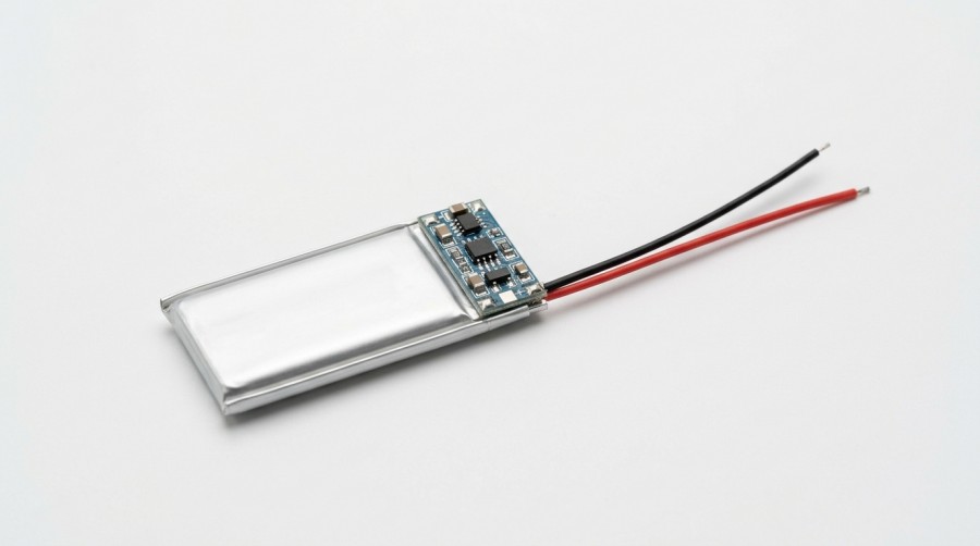
Custom low temperature lithium pouch battery cell with integrated BMS


Combine Thermal Insulation With Condensation Protection

Simply increasing sealing does not necessarily make a product suitable for ski environments. When equipment moves from a cold ski slope into a warm indoor environment, the temperature difference can cause condensation.

Battery compartments, connectors, FPC interfaces, and charging ports can incorporate gaskets, hydrophobic structures, pressure-equalization or venting solutions, and protective coatings. The water-resistance rating should match the actual use environment and be validated under realistic conditions.

Use the BMS to Manage Temperature, Power, and Warnings

Small battery packs still require clearly defined protection logic. A BMS can monitor cell temperature, voltage, current, and state of charge, and can limit current, issue warnings, or stop operation when charging conditions are unsuitable, overcurrent occurs, or temperature limits are exceeded.

For AI ski goggles connected to an app, low-temperature limitations, estimated remaining runtime, and charging status can also be communicated directly to the user.

Use Low-Temperature Testing Instead of Extrapolating From Room-Temperature Data

Battery manufacturing and complete-device development should include testing across the intended operating temperature range, such as 0°C, -10°C, and -20°C. Standby, video recording, AI recognition, wireless communication, high-brightness display, and anti-fog functions should be tested separately and in realistic combinations.

Testing should also monitor voltage behavior, enclosure temperature, protection trigger points, charging recovery behavior, and capacity performance after repeated cycling.


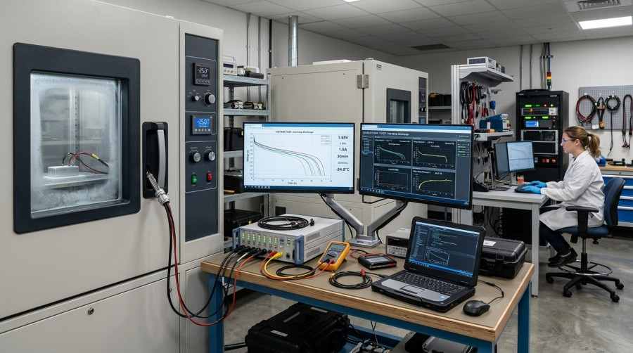
Environmental cold chamber battery performance testing in a lab


Common Questions About AI Ski Goggle Batteries in Cold Weather

Will AI Ski Goggle Battery Runtime Be Shorter Below Freezing?

It can be. Low temperatures affect lithium-ion transport and battery internal resistance. The actual reduction in runtime depends on cell chemistry, ambient temperature, load, the device’s thermal design, and battery ageing.

Runtime claims should ideally be supported by complete-device testing at the target operating temperature.

Does Warming AI Ski Goggles in a Pocket Before Use Help?

Keeping the battery relatively warm before use can generally help improve its initial output performance. However, once the device is operating, it will continue exchanging heat with the cold environment. The benefit therefore depends on battery placement, thermal insulation, and usage duration.

Can You Use a Power Bank to Charge Ski Goggles in Cold Weather?

Check the allowable charging temperature of both the device and its battery pack. If cell temperature is below the permitted charging range, the BMS may limit or stop charging even if the power bank can provide power. This is part of the battery protection strategy.

Do AI Features Use More Power Than Regular Ski Goggles?

Generally, yes. Image capture, displays, AI inference, wireless communication, and data storage all consume energy. During development, average power consumption can be reduced through processor low-power modes, on-demand wake-up, display brightness management, and tiered feature operation.

Can a Larger Battery Solve Cold-Weather Performance Problems?

A larger battery can provide more stored energy, but it also adds weight, volume, and charging time and may change the device’s weight distribution. Cold-weather runtime also depends on cell performance, insulation, power management, and BMS strategies, so battery sizing should be evaluated at the complete-system level.

About Himax Electronics

Himax Electronics specializes in custom battery and power solutions for demanding applications worldwide, including proprietary lithium-ion battery packs, power supplies, chargers, and accessories. For AI ski goggles, smart wearables, outdoor sports equipment, and other low-temperature applications, Himax Electronics can help customers evaluate battery-pack and power-system solutions based on target runtime, available installation space, operating temperature range, peak loads, charging method, and communication requirements, while supporting customized product development and project delivery.

Professional CCTV Surveillance System and Battery Backup Solution Banner

Commercial Disclosure: The Himax Electronics Editorial Team brings together expertise in battery products, power technologies, engineering applications, and global customer support to share practical information about battery technology, custom battery solutions, and power applications. Our content covers lithium-ion batteries, LiFePO4 batteries, battery pack design and selection, charging and power solutions, industry application guides, product updates, and official Himax Electronics news. Our goal is to help engineers, procurement professionals, and businesses better understand battery technologies and make informed decisions based on their specific application requirements. All content reflects the official editorial perspective of Himax Electronics and our commitment to providing reliable, flexible, and professional custom battery and power solutions for complex applications worldwide.

Key Takeaways

  • Confirm the voltage, power consumption, startup current, and target backup time of the entire surveillance system before calculating the required battery capacity.
  • Lead-acid and lithium-ion batteries each have suitable applications. Battery selection should consider installation space, temperature, cycling frequency, and maintenance requirements.
  • Rated Ah does not equal actual usable runtime. Discharge rate, low temperatures, battery ageing, and inverter losses can all affect operating time.
  • Outdoor enclosures, low-voltage equipment rooms, server rooms, and off-grid sites have different requirements for water resistance, dust protection, heat dissipation, flame resistance, and theft protection.
  • During procurement, verify the BMS, charger, cell source, protection functions, test reports, batch traceability, and after-sales support capabilities.
  • For lithium battery packs shipped internationally, confirm that transport documentation such as UN 38.3 corresponds to the actual battery model being shipped.

Introduction

When deploying a closed-circuit television (CCTV) surveillance system, cameras, NVRs, switches, and network equipment typically depend on continuous and stable power. Utility power interruptions, outdoor temperature fluctuations, system expansion, and cable voltage drop can all affect video retention and remote access. For this reason, purchasing batteries for CCTV surveillance systems should involve more than comparing rated capacity. System load, required backup time, installation environment, charging method, and maintenance conditions should all be evaluated.

Why Do CCTV Surveillance Systems Need Reliable Backup Batteries?

A CCTV surveillance system is not a single load. A typical installation may include cameras, infrared illuminators, PTZ mechanisms, power adapters, PoE switches, wireless bridges, NVRs, routers, and alarm integration equipment. Power consumption can also differ between daytime and nighttime operation. Infrared illumination, PTZ movement, intensive hard-drive writing, or network reconnection can temporarily increase power demand.

If backup battery capacity is selected based only on the rated power of the cameras, the calculation may overlook switches, conversion losses, and nighttime infrared loads, resulting in shorter-than-expected runtime during a power outage.


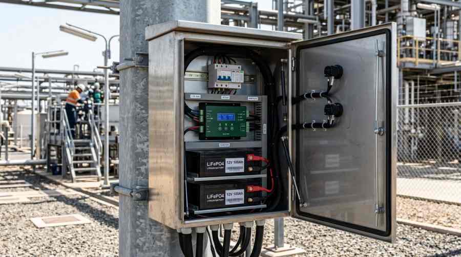
CCTV Camera Pole Installation with Weatherproof Battery Backup Enclosure


For warehouses, industrial parks, construction sites, retail stores, transportation hubs, and remote sites, power continuity directly affects the completeness of recorded footage and the ability to review security events.

Before Purchasing: Calculate CCTV Battery Capacity First

Battery capacity is commonly expressed in Ah (amp-hours), but proper sizing also requires consideration of system voltage and efficiency. An initial estimate can use the following formula:

Required Battery Capacity (Ah) ≈ Average System Power (W) × Backup Time (h) ÷ Battery System Voltage (V) ÷ System Efficiency × Safety Margin Factor

For example, consider a 12V surveillance system with an average load of 60W and a target backup time of 8 hours. If overall system efficiency is estimated at 0.85 and a safety margin factor of 1.25 is applied, the theoretical capacity would be approximately:

60 × 8 ÷ 12 ÷ 0.85 × 1.25 ≈ 58.8Ah

In an actual project, the battery discharge curve, ambient temperature, ageing allowance, and equipment startup current should also be considered when selecting a battery specification close to or above the calculated requirement.

Do not estimate runtime based only on a label such as “12V 100Ah.” The amount of usable capacity can vary depending on battery chemistry, discharge current, and cutoff voltage.

Variable Affecting Runtime Common Effect on CCTV Systems Information to Request During Procurement
Average and peak loads Infrared lighting, PTZ movement, and hard-drive activity can increase power consumption Time-based power profile and startup current data
Battery system voltage 12V, 24V, and 48V systems differ in cable losses and equipment compatibility System wiring diagram and operating voltage range
Discharge rate Usable capacity of some batteries decreases at higher discharge currents Discharge curves at relevant C-rates
Temperature Low temperatures can reduce discharge performance, while high temperatures can accelerate ageing Operating, charging, and discharging temperature ranges
Conversion efficiency UPS systems, inverters, and PoE equipment introduce energy losses Conversion efficiency curves and standby power consumption
Battery condition and ageing Long-term float charging or frequent cycling can change usable capacity Cycle life, float life, and warranty terms

How Should You Choose Between Lead-Acid and Lithium-Ion Batteries?

Common backup power solutions for surveillance systems include valve-regulated lead-acid (VRLA) batteries, lithium iron phosphate (LiFePO4) batteries, and compatible UPS or DC power systems. No single battery solution is suitable for every CCTV project. The key is understanding the application’s operating conditions.

Comparison Factor VRLA Battery LiFePO4 Battery
Initial purchase cost Usually easier to keep initial costs lower Typically higher than lead-acid solutions
Capacity relative to weight Lower Higher, which can reduce enclosure weight
Cycling applications Commonly used for standby and float applications Well suited to applications with more frequent charge-discharge cycles
Installation space Requires more space for the same backup requirement Higher space efficiency
BMS requirements Generally does not use an electronic BMS BMS protection and communication capabilities should be evaluated
Low-temperature charging Generally offers a broader operating range, but specifications still apply Requires evaluation of cell limitations and BMS low-temperature charging strategies
Replacement and maintenance Widely used and commonly available for replacement Voltage, charging logic, and communication compatibility should be verified

If the application primarily requires long-term standby with float charging, has sufficient installation space, and uses an existing UPS designed for lead-acid batteries, a VRLA solution may be easier to integrate.

If space is limited, the battery will be cycled more frequently, manual maintenance is difficult, or reducing transportation and installation weight is important, a LiFePO4 battery pack may be worth evaluating.


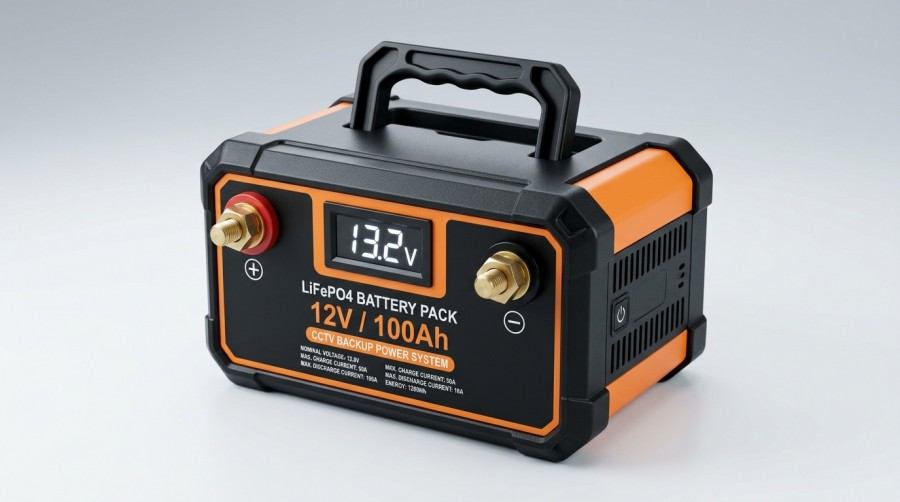
12V LiFePO4 Lithium Battery Pack for CCTV Surveillance Backup


Before purchasing, verify the charger’s constant-current/constant-voltage parameters, float-charging strategy, and low-temperature limitations. Charging equipment designed for another battery chemistry should not be connected directly to a lithium battery pack without confirming compatibility.

Focus on Voltage Compatibility, Not Just Capacity

Common DC voltages for CCTV surveillance systems include 12V, 24V, and 48V. PoE systems also involve switch output voltage, cable length, and the voltage available at the powered device. The battery pack’s nominal voltage must be checked against the allowable input range of each device.

For example, a “12V lithium battery” may use a 4-series LiFePO4 configuration with a fully charged voltage approaching 14.6V, while some equipment may be sensitive to the upper input-voltage limit.

For 24V or 48V systems, the operating ranges of the UPS, PoE switch, DC-DC converter, and end loads should also be verified. With long-distance power transmission, voltage drop caused by cable resistance may cause remote cameras to disconnect or restart repeatedly.

Battery buyers should provide the manufacturer with information such as the equipment list, rated and peak power consumption, operating voltage, cable length, target backup time, temperature range, whether an inverter is used, and whether remote communication is required. This makes it easier to develop a battery-pack configuration that matches the actual system.

What Safety, Protection, and Certification Documents Should You Review?

For lithium-ion CCTV backup batteries, cell quality is only one part of battery safety. The complete battery pack also relies on the BMS, wiring harnesses, connectors, fuses or other protective devices, mechanical components, and charging strategy to reduce risk.

Key areas to verify include protection logic for overcharge, over-discharge, overcurrent, short circuit, temperature, and cell consistency. Buyers should also understand whether the system supports recovery, alarms, or communication-based fault reporting after a protection event occurs.

IEC 62619:2022, published by the International Electrotechnical Commission, covers safety requirements and testing for secondary lithium cells and batteries used in industrial applications, including stationary applications. For lithium battery solutions used in equipment rooms, outdoor cabinets, communications infrastructure, or security backup systems, relevant testing capabilities can be considered as part of supplier qualification.

If the battery pack will be shipped by air, sea, or across international borders, buyers should also review lithium battery transportation requirements in the UNECE Manual of Tests and Criteria. UN 38.3 documentation should correspond to the actual cells, battery-pack configuration, and model being shipped. If the model, capacity, or critical materials change, outdated documentation that does not match the actual product should not simply be reused.

What Else Should You Consider for Outdoor CCTV Batteries?

Outdoor surveillance power enclosures may be exposed to sunlight, high temperatures, rain, dust, condensation, salt spray, and vandalism. Even if the battery itself performs well in room-temperature testing, an unsuitable enclosure or inadequate thermal design can contribute to shortened service life, protection shutdowns, or connector corrosion.

Application Environment Primary Risks Recommended Considerations
Outdoor pole-mounted enclosure Sun exposure, rain, condensation, theft or vandalism Protection rating, locks, cable sealing, ventilation, and sun shielding
Construction and industrial sites Dust, vibration, and unstable utility power Vibration-resistant structure, secure terminals, and wide-input-range chargers
Coastal areas Salt-spray corrosion Corrosion-resistant materials, connector plating, and enclosure sealing
Cold-climate regions Reduced discharge capability and low-temperature charging risks Low-temperature discharge curves, heating strategies, and BMS temperature-control logic
Equipment or server rooms Heat buildup and insufficient maintenance Ventilation clearance, temperature alarms, and periodic capacity checks
Low-temperature charging Generally offers a broader operating range, but specifications still apply Requires evaluation of cell limitations and BMS low-temperature charging strategies
Replacement and maintenance Widely used and commonly available for replacement Voltage, charging logic, and communication compatibility should be verified

Procurement specifications can require suppliers to clearly state charging, discharging, and storage temperature ranges, recommended installation clearances, and maintenance intervals.

For high-temperature enclosures or low-temperature sites, prototype validation under actual environmental conditions is preferable to relying solely on laboratory room-temperature data.


IP66 Outdoor Weatherproof Enclosure for CCTV Battery and BMS Controller


Don’t Overlook Chargers, UPS Systems, and Remote Monitoring

A reliable CCTV backup power system should evaluate the battery, charger, UPS, or DC power supply as an integrated system.

If charger voltage is too high, it can place additional stress on the battery. If it is too low, the battery may remain undercharged. The standby power consumption of the UPS itself can also affect final backup runtime.

For distributed CCTV installations, a BMS capable of reporting SOC, voltage, temperature, alarm status, and cycle count can help maintenance teams identify abnormal conditions earlier.

During procurement, buyers can ask suppliers whether the battery supports RS485, CAN, Bluetooth, or dry-contact alarms; whether it can integrate with an existing monitoring platform; how low-state-of-charge or temperature alarms are communicated; and whether parameters need to be reconfigured after battery replacement. These factors can affect long-term inspection and maintenance efficiency.

Supplier Evaluation Checklist for CCTV Surveillance System Batteries

  • Verify that the cells, battery pack, BMS, and charger have clear model identification and batch traceability.
  • Request capacity testing, ageing test data, and discharge curves that correspond to the target specification.
  • Confirm whether the supplier can explain expected battery performance under the target temperature and load conditions.
  • Check whether customization is available for system voltage, enclosure dimensions, connectors, wire-harness length, and communication protocols.
  • Verify whether the supplier can provide transportation documentation, packaging requirements, and dangerous-goods shipping support.
  • Confirm whether warranty terms clearly address capacity degradation, BMS failures, mechanical components, and technical support procedures.
  • Determine whether small-batch prototype testing and post-delivery technical support are available.

Frequently Asked Questions About CCTV Surveillance System Batteries

How Long Can a 12V 100Ah Battery Power a CCTV System?

Runtime cannot be determined from capacity alone. If the system load is 100W and there are additional inverter and cable losses, actual runtime will also depend on battery chemistry, discharge current, temperature, and battery ageing.

Supplier discharge curves and complete-system testing should be used as the primary references.

Why Does an Outdoor CCTV Battery Have Shorter Runtime in Winter?

Low temperatures can slow electrochemical reactions and reduce usable capacity, while load-side voltage may also drop earlier.

If the battery is charged in cold conditions, the temperature limits specified for the cells and BMS should also be followed. The system can be optimized through insulated enclosures, temperature-control strategies, additional capacity margin, or cells designed for the required low-temperature operating range.

Does UN 38.3 Mean a Battery Is Suitable for Every CCTV Project?

No. UN 38.3 primarily relates to lithium battery transportation testing. It does not replace project-specific validation for electrical compatibility, safety design, environmental durability, cycle life, or actual load conditions.

During procurement, transportation documentation should be reviewed alongside the electrical design and prototype test results.

Himax Electronics

Himax Electronics specializes in customized battery and power solutions for demanding applications worldwide, including proprietary lithium-ion battery packs, power supplies, chargers, and related accessories.

For CCTV surveillance systems, outdoor security equipment, communications equipment, and other industrial applications, Himax Electronics can help customers evaluate battery-pack and power-system configurations based on load requirements, voltage, backup time, installation space, environmental temperature, and communication requirements, while providing customized support for project development and delivery.

International air freight logistics terminal for lithium battery shipments

Commercial Disclosure: The Himax Electronics Editorial Team brings together expertise in battery products, power technologies, engineering applications, and global customer support to share practical information about battery technology, custom battery solutions, and power applications. Our content covers lithium-ion batteries, LiFePO4 batteries, battery pack design and selection, charging and power solutions, industry application guides, product updates, and official Himax Electronics news. Our goal is to help engineers, procurement professionals, and businesses better understand battery technologies and make informed decisions based on their specific application requirements. All content reflects the official editorial perspective of Himax Electronics and our commitment to providing reliable, flexible, and professional custom battery and power solutions for complex applications worldwide.

Key Takeaways

  • Lithium battery shipping requirements depend on the battery type, rated energy, packaging configuration, mode of transportation, and product condition. A shipping solution used for one order should not automatically be applied to another.
  • UN 38.3 test reports, test summaries, and SDS documents serve different purposes. Buyers should verify that the documents correspond to the actual model being shipped.
  • A cell passing the required tests does not necessarily mean that a custom battery pack assembled with that cell has met the applicable transportation testing requirements.
  • Air-shipping state-of-charge requirements differ depending on whether batteries are shipped by themselves, packed with equipment, or contained in equipment.
  • Packaging design, manufacturing changes, and shipping documentation should be incorporated into project management. Confirming these requirements early can help reduce rework, returned shipments, and delivery delays.

Introduction

For OEMs and buyers, lithium battery shipping affects more than freight costs. It can also influence prototype validation, equipment assembly, and order delivery. Even if a battery pack has completed performance testing, inaccurate transportation classification, mismatched model information in documentation, or noncompliant packaging may prevent it from shipping as planned.

From a battery manufacturing perspective, transportation planning should begin during the product-definition stage. Cell selection, series-parallel configuration, rated energy, enclosure design, and the form in which the product will be shipped can all affect subsequent transportation arrangements.

This article focuses on commercial shipments of conventional lithium batteries and equipment containing batteries. The regulatory information is based on publicly available information for 2026. Specific shipments should be reviewed against the rules in effect at the time of shipment, applicable national requirements, and individual carrier policies. Passenger baggage, battery-powered vehicles, and certain other products are subject to separate requirements.

Lithium Battery Shipping Classification: Start by Identifying What Is Being Shipped

Even when the same type of lithium battery is involved, shipping the battery by itself and shipping it installed in equipment may result in different packaging and handling requirements. When requesting a quote, OEMs should accurately describe the actual shipping configuration.

Battery Type Shipping Configuration Common UN Number
Lithium-ion battery Batteries shipped by themselves UN 3480
Lithium-ion battery Packed with the equipment they power, but not installed UN 3481
Lithium-ion battery Contained in equipment UN 3481
Lithium metal battery Batteries shipped by themselves UN 3090
Lithium metal battery Packed with or contained in the equipment they power UN 3091

These classifications apply to conventional battery shipments and do not cover every special product or circumstance. Although the two UN 3481 configurations share the same UN number, different air-transport packing instructions apply, so the actual shipping configuration still needs to be clearly identified in the documentation. Reference: IATA Lithium Battery Shipping Information

During procurement discussions, avoid vague descriptions such as “product with battery.” A clearer description would be: “Rechargeable lithium-ion battery pack, not installed in the equipment, packed in the same outer packaging as the equipment it powers.” This helps the manufacturer and logistics provider determine the applicable shipping requirements.


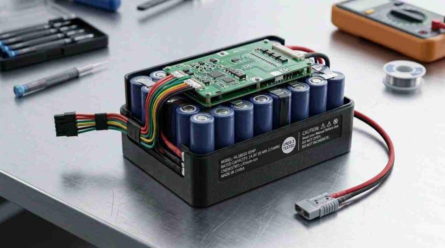
Custom lithium-ion battery pack with protection circuit board on industrial workbench


Why Should Procurement Documents Specify Wh?

Providing only “5000mAh” does not fully describe the energy of a battery pack. Battery packs with the same capacity but different voltages have different rated energy.

A common conversion is:

Rated Energy (Wh) = Nominal Voltage (V) × Rated Capacity (Ah)

For example, a battery pack with a nominal voltage of 14.8V and a rated capacity of 5Ah has a rated energy of 74Wh. The calculation should use nominal voltage, and mAh should be converted to Ah before calculating.

Rated energy is an important parameter when determining lithium-ion battery shipping requirements, but it is not the only factor. A battery should not be assumed to fall outside transportation requirements simply because it has a relatively small capacity or falls below a particular Wh value. Battery type, quantity per package, shipping configuration, and applicable provisions must also be considered.

Manufacturers should manage voltage, capacity, and Wh information consistently across product specifications, labels, and transportation documents. This helps prevent situations in which a specification sheet has been updated while the outer packaging or shipping documentation still contains outdated parameters.

What Is the Difference Between a UN 38.3 Test Summary, Test Report, and SDS?

Lithium battery export documents are sometimes collectively referred to as “battery certificates,” but different documents serve different purposes.

Document or Information Primary Purpose What OEMs and Buyers Should Verify
UN 38.3 test report Records the applicable tests and results for a particular design type Model, sample description, report number, and conclusion
UN 38.3 test summary Provides standardized traceability information to the supply chain Manufacturer, test laboratory, model, and related report information
SDS, commonly called MSDS Provides hazard, handling, storage, and emergency-response information Whether it corresponds to the actual product and battery chemistry
Transportation assessment or carrier-review documents Used to review cargo for a particular shipping channel Applicable transportation mode, model, document version, and acceptance conditions
Dangerous goods declaration documents Used for transportation declarations when applicable Proper shipping name, classification, quantity, and packaging information

An SDS does not replace UN 38.3 testing evidence, nor does it independently prove that a particular shipment meets all applicable transportation requirements. Not every shipment requires the same combination of documents, so the required documentation should be confirmed for the specific shipping route.

UN 38.3 is a transportation-related design-type test. Manufacturers and subsequent distributors are required to make the applicable test summary available so that the supply chain can identify and trace the corresponding battery design. The test summary should not be interpreted as evidence that every production batch has been retested. Reference: PHMSA Lithium Battery Test Summary Requirements

If the Cells Have Passed UN 38.3, Does a Custom Battery Pack Still Need to Be Evaluated?

Yes. Cells and battery packs are different product levels. Battery-pack assembly introduces interconnections, protection circuitry, enclosures, and other components, so a cell-level report alone should not be used to conclude that the complete pack meets the applicable requirements.

OEMs should ask the manufacturer to confirm which tests apply to the battery-pack design and whether existing reports cover the actual configuration being shipped. Changes to the cell model, series-parallel configuration, or protection design should also trigger a change assessment.

Design changes that may affect UN 38.3 test results may require testing as a new type. Keeping the same model name does not, by itself, mean that existing documentation remains applicable. Reference: PHMSA Lithium Battery Shipping Guide

From a project-management perspective, maintaining revision records for custom battery packs is recommended. The bill of materials, structural drawings, test documentation, and labels should be linked to the applicable product revision. This allows buyers to verify whether repeat orders or changes in supply batches remain within the configuration that has already been evaluated.

How Do Air-Shipment State-of-Charge Requirements Differ in 2026?

State of charge, commonly abbreviated as SoC, describes the battery’s current charge level relative to its rated capacity. When discussing SoC requirements for lithium battery air shipments, the packaging configuration should be identified first.

Lithium-Ion Battery Air-Shipment Configuration Packing Instruction Overview of 2026 SoC Requirements
Batteries shipped by themselves PI 965 Generally limited to no more than 30% SoC; shipments above this level require approval under the applicable provisions
Packed with equipment but not installed PI 966 Section I is limited to no more than 30% SoC; under Section II, cells and batteries above 2.7Wh are limited to no more than 30% SoC; exceeding the applicable limit requires approval and compliance with the relevant provisions
Contained in equipment PI 967 SoC of no more than 30%, or an indicated battery capacity of no more than 25%, is recommended; this is not a uniform mandatory requirement under this packing instruction

It is therefore inaccurate to conclude that “all equipment containing lithium batteries must be below 30% SoC for air transportation.” The percentage displayed by a device should also not automatically be treated as the battery’s actual SoC. Reference: IATA 2026 Battery Guidance Document

For manufacturers, SoC control also affects production planning. Capacity reference points, charge and discharge procedures, measurement tolerances, and packing times should be clearly defined, while BMS quiescent current and expected transit time should also be considered. For battery chemistries with relatively flat voltage curves, a single open-circuit voltage measurement may not provide sufficiently reliable SoC control for shipping purposes.


Engineer testing state of charge on lithium battery in laboratory


What Should You Consider When Packaging Lithium Batteries for Shipping?

Packaging should be designed around risks such as short circuits, movement, compression, and accidental activation rather than simply preventing cosmetic damage. Specific packaging performance, quantity limits, marks, and labels should be confirmed according to the applicable transportation requirements. Reference: IATA Lithium Battery Shipping Guidance

During the manufacturing stage, key considerations include:

  • Terminal protection:Use suitable insulation or protective components to prevent exposed terminals from contacting other batteries or conductive materials.
  • Internal restraint:Design internal packaging according to battery weight and shape, and verify that the battery remains securely positioned after handling and vibration.
  • Wire and harness protection:Prevent cables from being pulled, pinched, or continuously rubbing against enclosure edges.
  • Equipment condition:For equipment containing batteries, check switch protection and available transport modes to reduce the possibility of accidental activation.
  • Outer-package information:Include packaging photos, label revisions, and package quantities in the pre-shipment review process.

Bubble wrap, ordinary cardboard boxes, or boxes bearing UN markings do not independently demonstrate that a packaging solution meets applicable requirements unless they are evaluated in the context of the actual shipment.

If packaging materials, quantities per package, or battery weight change, the original packaging solution should be reviewed again for continued applicability.


UN rated dangerous goods packaging box for lithium battery transportation


Can the Same Shipping Solution Be Used for Ocean Freight, Air Freight, and Returns?

Not automatically. When the mode of transportation changes, packaging, documentation, and carrier conditions need to be reviewed again. International ocean shipments should be checked against the applicable International Maritime Dangerous Goods (IMDG) Code. Amendment 42-24 of the IMDG Code became mandatory on January 1, 2026. Reference: IMO IMDG Code Information

When OEMs compare shipping options, they should consider packaging costs, document-preparation time, booking lead times, warehousing, and destination-delivery costs rather than comparing freight rates per kilogram alone.

Returns should also be managed separately. An unused battery being returned under normal conditions may be treated differently from a battery that is swollen, leaking, damaged, or recalled because of a safety defect. Damaged or defective batteries that may generate heat, catch fire, or short-circuit are subject to air-transport restrictions and cannot simply be shipped using the same process as new batteries. Reference: IATA 2026 Battery Guidance Document

What Information Should Be Confirmed Before Purchasing to Reduce Delivery Delays?

Consider including the following information in the RFQ or order attachment so that the manufacturer, procurement team, and logistics team are all working from the same version.

Project Stage Information to Confirm
Project RFQ Battery type, voltage, capacity, Wh, weight, and destination
Design confirmation Cell and battery-pack model, design revision, and applicable test coverage
Prototype shipment Whether applicable testing has been completed, shipping configuration, and intended transportation route
Mass-production planning Packaging solution, SoC control, labels, and documentation lead time
Packing and delivery Quantity, model, document revision, and carrier-review status
After-sales returns Battery condition, fault description, photos, and available shipping channels

Responsibilities should also be clearly defined for providing product data, preparing packaging, completing applicable declarations, and verifying destination requirements. Logistics providers need accurate information from the manufacturer, while buyers should communicate the actual application and delivery destination in a timely manner.

FAQ: Lithium Battery Shipping Questions for OEMs and Buyers

  1. Can a Few R&D Samples Be Shipped Without UN 38.3 Testing?

This cannot be determined based only on the small quantity involved. Prototypes and low-production-run batteries may be covered by specific transportation provisions, but these have applicable conditions and should not be treated as a general exemption from dangerous goods requirements. The available shipping route and any required approvals should be confirmed during the prototype planning stage. Reference: PHMSA Lithium Battery Shipping Guide

  1. Does Having a UN 38.3 Test Summary Mean a Carrier Will Definitely Accept the Shipment?

No. A test summary addresses traceability of the battery design and testing. Actual carrier acceptance also depends on packaging, quantity, SoC, routing, and carrier-specific requirements. Buyers should confirm the shipping channel before establishing the final delivery date.

  1. Does a UN 38.3 Test Summary Need to Be Reissued for Every Shipment?

Not simply because a new production batch is being shipped. However, the test summary should correspond to the current design and contain accurate information. If the product changes, the continued applicability of the existing documentation should be reassessed.

  1. If a Standalone Battery Is Packed With a Charger, Can It Be Classified as “Packed With Equipment”?

Not solely because a charger is included in the same package. “Packed with equipment” involves the relationship between the battery and the equipment it is intended to power. The actual configuration should be classified by personnel familiar with the applicable requirements; adding an accessory does not change the nature of the shipment.

  1. What Information Is Needed Before Requesting an International Lithium Battery Shipping Quote?

Consider providing the product specification, Wh rating, weight, quantity, packaging configuration, test summary, product condition, origin, and destination. Clearly stating whether the batteries are shipped separately or installed in equipment can help logistics providers provide a more actionable quote and delivery estimate.

  1. Why Is the Battery Production Lead Time Different From the Earliest Shipping Date?

After manufacturing is complete, SoC adjustment, documentation review, packaging verification, and carrier approval may still be required. Custom battery projects should include these steps in the delivery schedule rather than planning equipment assembly solely around the battery production completion date.

About Himax Electronics

Himax Electronics specializes in customized battery and power solutions for a wide range of demanding applications worldwide, including proprietary lithium-ion battery packs, power supplies, chargers, and accessories designed for specific industry requirements. For projects involving prototype validation, volume purchasing, and cross-border delivery, buyers can provide Himax Electronics with application requirements, target markets, and intended shipping methods during the solution-development stage. Confirming product configurations and delivery requirements early helps provide adequate time for subsequent testing, packaging, and transportation preparation.

High-capacity commercial drone lithium battery pack on a diagnostic station workbench.

Commercial Disclosure: The Himax Electronics Editorial Team brings together expertise in battery products, power technologies, engineering applications, and global customer support to share practical information about battery technology, custom battery solutions, and power applications. Our content covers lithium-ion batteries, LiFePO4 batteries, battery pack design and selection, charging and power solutions, industry application guides, product updates, and official Himax Electronics news. Our goal is to help engineers, procurement professionals, and businesses better understand battery technologies and make informed decisions based on their specific application requirements. All content reflects the official editorial perspective of Himax Electronics and our commitment to providing reliable, flexible, and professional custom battery and power solutions for complex applications worldwide.

Key Takeaways

  • Drone battery internal resistance is typically expressed in milliohms (mΩ), and readings should be compared under the same test conditions, either across batteries or against historical data.
  • Before testing, standardize battery temperature, state of charge, rest time, test equipment, and measurement points to avoid mistaking environmental differences for battery ageing.
  • Common measurement methods include AC internal resistance testing, DC pulse testing, and electrochemical impedance spectroscopy (EIS). Results obtained using different methods should not be compared directly.
  • Similar internal resistance across individual cells does not necessarily mean the entire battery pack is healthy. Cell voltage differences, connection resistance, the protection board, and wiring condition should also be checked.
  • A continuing increase in internal resistance, unusually high resistance in one cell, greater voltage sag during flight, or abnormal heat generation can indicate that further inspection is needed.
  • During testing, never short-circuit, puncture, disassemble, or use incompatible test fixtures on the battery. Batteries that are swollen, damaged, or abnormally hot should not undergo further charge or discharge testing.

Introduction

Drone battery internal resistance is an important reference parameter for evaluating power-delivery capability and cell consistency. In applications such as aerial photography, inspection, surveying and mapping, and agricultural spraying, batteries may experience high current during takeoff, rapid acceleration, and hovering in strong winds. As internal resistance increases, effects such as greater voltage sag under load, increased heat generation, and reduced usable flight time may become more noticeable.


High-capacity commercial drone lithium battery pack on a diagnostic station workbench.


However, internal resistance is not a single “battery health score.” Cell chemistry, capacity, series-parallel configuration, state of charge (SOC), temperature, test frequency, and instrument algorithms can all affect the reading. When evaluating the health of a drone lithium battery, internal resistance trends should be considered together with capacity, cell voltage differences, cycle records, flight logs, and physical condition.

  1. What Is Drone Battery Internal Resistance?

Battery internal resistance can be understood as the resistance to current flow within the battery and its electrical connection path. In a drone lithium battery, this resistance does not come only from the cells themselves. It may also include resistance from tabs, welds, nickel strips, wires, connectors, protection boards, and smart battery management modules.

When drone motors suddenly demand more power, the increase in current causes the battery voltage to drop. A simplified relationship can be used to understand this effect:

Voltage Sag Under Load ≈ Discharge Current × Equivalent Internal Resistance

For example, under otherwise similar conditions, a battery pack with higher equivalent internal resistance may experience greater instantaneous voltage sag during high-current takeoff or flight against strong winds. If the voltage drop becomes excessive, the flight controller may trigger low-voltage protection earlier, creating a situation where the battery appears to have remaining charge but provides less usable flight time than expected.

From a battery manufacturing and quality-control perspective, internal resistance is more useful for monitoring trends, identifying outliers, and verifying batch consistency than for establishing a universal pass/fail threshold without reference to the battery specifications.

  1. Why Does Drone Battery Internal Resistance Change?

As lithium-ion batteries undergo storage, charge-discharge cycling, and high-load operation, the condition of internal materials and interfaces gradually changes. Publicly available information from the U.S. Department of Energy indicates that battery ageing can involve both capacity loss and impedance growth, while factors such as higher temperatures, higher cutoff voltages, and wider cycling voltage windows can affect ageing behavior. U.S. Department of Energy Battery Diagnostics Research

Changes in the internal resistance of a drone battery are commonly associated with the following factors:

Factor Possible Effect on Internal Resistance Readings Recommended Check
Increasing cycle count Electrochemical impedance may gradually increase Review cycle records and compare them with early baseline values
High-temperature storage or operation Short-term readings may fluctuate, while long-term exposure may accelerate ageing Record battery surface temperature during testing
Low-temperature testing Internal resistance generally increases noticeably Do not directly compare with historical room-temperature data
Different SOC levels Resistance varies across the battery’s state-of-charge range Standardize testing within a defined SOC range, such as 40% to 60%
High-current operation May result in greater temperature rise and voltage sag under load Review voltage curves together with flight logs
Connector oxidation or poor contact Equivalent pack resistance may increase Inspect connectors, wiring, welds, and terminals
Reduced cell consistency One cell may become the weak point in the pack Review individual cell voltages and cell-level internal resistance data

NASA’s publicly available battery ageing datasets also show that differences in depth of discharge, rest periods, and individual cells can result in different states of health even at the same cycle count. A single resistance reading therefore should not replace a more complete battery health assessment. NASA Li-Ion Battery Aging Datasets

  1. How Do You Measure Drone Battery Internal Resistance?

Method 1: Use an AC Internal Resistance Meter

An AC internal resistance meter typically applies a small AC signal at a fixed frequency to measure battery impedance. The method is relatively fast and is suitable for incoming inspection, routine screening, and batch-level trend monitoring. Many instruments display the result directly in mΩ, but readings may vary depending on the instrument brand, test frequency, fixture contact method, and calculation algorithm.


Engineer using an AC internal resistance meter with Kelvin probes to test a drone battery terminal.


During testing, the fixture should make stable contact with the battery’s main positive and negative terminals. If the battery has a dedicated diagnostic or balance connector, whether it can be used for measurement should be determined from the product documentation. Do not pry open the enclosure or access internal terminals that are not designed for user operation simply to make testing easier.

Method 2: DC Pulse Testing

The DC pulse method applies a known load current, records the voltage before and during the load pulse, and then estimates DC internal resistance. A simplified formula is:

DC Internal Resistance R ≈ (Resting Voltage U₁ − Pulse-Load Voltage U₂) ÷ Pulse Current I

For example, if the battery’s resting voltage is 15.80V and the voltage drops to 15.50V under a 10A pulse:

(15.80 − 15.50) ÷ 10 = 0.03Ω, or 30mΩ

This method more closely reflects battery behavior during the high-current discharge conditions encountered by drones. However, pulse current, pulse duration, sampling rate, and battery temperature all affect the result. For smart battery packs, protection-board control strategies may also influence the response. The resulting value therefore represents the equivalent internal resistance of the battery system, not the AC internal resistance of a bare cell.

Method 3: Electrochemical Impedance Spectroscopy (EIS)

EIS measures impedance response across multiple frequency ranges and can help engineers involved in R&D, failure analysis, and ageing studies distinguish among ohmic resistance, charge-transfer resistance, and diffusion-related characteristics. It requires specialized equipment, test fixtures, and expertise in interpreting the data, so EIS results are generally not suitable as a single quick diagnostic indicator for everyday users.

Measurement Method Typical Application Advantages Limitations
AC internal resistance Incoming inspection, routine sampling, trend monitoring Fast and convenient for building historical records Readings from different instruments and frequencies should not be compared directly
DC pulse testing Simulating voltage sag and evaluating high-power performance More closely related to drone discharge conditions Pulse parameters, temperature, and SOC must be controlled
EIS R&D validation, failure analysis, ageing studies Provides more detailed impedance information Requires specialized equipment, modeling, and data interpretation
Flight log analysis Maintenance troubleshooting, fleet management Shows actual voltage sag and power-demand behavior Results are affected by payload, wind speed, and flight profile
  1. A Standardized Process for Testing Drone Battery Internal Resistance

To make measurements taken on different dates comparable, establish a standardized testing procedure. The following process is suitable for routine screening, but specific voltage, rest-time, and temperature requirements should always follow the battery specifications and test-equipment instructions.

  1. Inspect the battery. Confirm that there is no swelling, cracking, leakage, scorching, unusual odor, loose terminals, or damaged wiring. If any abnormal condition is found, do not continue with charge, discharge, or internal resistance testing.
  2. Standardize the state of charge. Batteries from the same batch can be brought to a similar SOC range, such as 40% to 60%. Readings obtained at different SOC levels should be recorded separately.
  3. Stabilize the temperature. Allow the battery to rest in a stable environment until its surface temperature approaches the test-environment temperature. Batteries that have just completed a flight, charging session, or prolonged sun exposure should be allowed to cool.
  4. Clean the terminals. Make sure the terminals are dry and free from visible oxidation, oil, or debris. The test fixture should make firm contact with a consistent contact area.
  5. Use a consistent test method. For long-term tracking, use the same instrument or instrument model, test mode, fixture, and measurement points.
  6. Repeat the measurement. Take several consecutive readings and record the average and range of variation. If readings fluctuate significantly, inspect fixture contact, terminal condition, and instrument calibration.
  7. Evaluate multiple parameters together. Record individual cell voltage, pack voltage, capacity-test results, cycle count, in-flight voltage sag, temperature rise, and fault codes alongside internal resistance.
  8. What Do Internal Resistance Test Results Reveal About Drone Battery Health?

Internal resistance data is most useful when compared with the battery’s own baseline. This baseline may come from new-battery acceptance testing, stable samples from the same model and production batch, or early records from the same battery under standardized conditions.

Test Result What It May Indicate Recommended Next Step Limitations
Internal resistance remains close to the historical baseline with small differences between cells Power capability may remain within the normal range of variation Continue maintaining records under standardized conditions Readings from different instruments and frequencies should not be compared directly
Internal resistance gradually increases while capacity still meets mission requirements Normal ageing or changes in operating conditions may be occurring Shorten the inspection interval and monitor in-flight voltage sag Pulse parameters, temperature, and SOC must be controlled
One cell shows significantly higher internal resistance Cell ageing, connection problems, or measurement error may be involved Retest and check cell voltage differences, terminals, and temperature Requires specialized equipment, modeling, and data interpretation
Pack resistance increases while individual cell data appears normal Connectors, wiring, the protection board, or welded connections may require inspection Have the system inspected by qualified personnel Results are affected by payload, wind speed, and flight profile
Internal resistance increases while capacity decreases Battery health may be deteriorating Adjust the operating and retirement plan based on mission power requirements
Internal resistance increases together with swelling, overheating, or alarms A potential safety issue may be present Stop using the battery, isolate it, and contact after-sales support or a professional recycling service

It is important to emphasize that there is no single fixed milliohm threshold that can be universally applied across batteries with different capacities, discharge-rate capabilities, and chemistries. For example, a high-capacity drone battery with multiple cells in parallel and a small racing-drone battery may have very different pack-level internal resistance values even when both are in similar states of health. Monitoring trends within the same battery model at similar temperatures and SOC levels generally provides more useful information.


Drone technician reviewing battery internal resistance trends and health diagnostics on a tablet.


  1. Drone Battery Internal Resistance Testing FAQ

Is Lower Drone Battery Internal Resistance Always Better?

Under the same battery model, temperature, SOC, and test method, lower internal resistance generally means less voltage sag and lower resistive heat loss under load. However, internal resistance is not the only performance criterion. The battery must also meet requirements for capacity, discharge rate, temperature rise, cycle life, weight, and protection strategy.

Can I Measure Internal Resistance Immediately After a Flight?

A battery that has just completed a flight is still changing in temperature and SOC, so its reading may differ from one taken after resting at room temperature. If you are building a comparable database, test after a defined rest period and under standardized temperature conditions. If the goal is to evaluate actual high-load flight behavior, record those operating conditions separately.

Can I Measure Drone Battery Internal Resistance With a Multimeter?

A standard multimeter generally measures DC resistance and cannot reliably determine the equivalent internal resistance of a lithium battery under operating conditions. It is also not suitable for simply connecting across the battery terminals to make this type of assessment. DC pulse testing requires a controlled electronic load, sufficient sampling capability, and appropriate safety fixtures.

Can a Smart Drone Battery Show Internal Resistance Directly in an App?

Some smart batteries or flight-control systems record state of health, cycle count, individual cell voltage differences, temperature, and fault codes. Whether internal resistance is displayed, and how it is calculated, depends on the manufacturer. Health information shown in an app can be useful for maintenance, but it should still be interpreted according to the manufacturer’s diagnostic procedures.

If Cell Voltage Differences Are Normal, Does That Mean Internal Resistance Is Also Normal?

Not necessarily. Similar cell voltages may indicate acceptable consistency under static or low-load conditions, but a cell with higher internal resistance may still experience greater instantaneous voltage sag under high-current discharge. For high-power drones, cell voltage differences, internal resistance trends, and load-voltage curves should be evaluated together.

Can a Drone Battery With High Internal Resistance Still Be Used for Flight?

This should be evaluated based on how much the resistance has increased, how quickly it is changing, remaining capacity, temperature rise, mission risk, and manufacturer requirements. If high internal resistance is accompanied by battery swelling, significant overheating, abnormal warnings, terminal damage, or excessive voltage sag under load, the battery should be removed from service and inspected. For payload operations, flights over populated areas, or mission-critical applications, battery maintenance criteria should be more conservative.

Himax Electronics: Manage Drone Battery Health Through Data Trends

The value of measuring drone battery internal resistance lies in turning otherwise invisible changes in power-delivery capability into data that can be recorded and compared. For fleet operators and equipment manufacturers, establishing standardized SOC, temperature, instruments, fixtures, and recording procedures—and combining those records with capacity, cell voltage differences, flight logs, and physical inspections—can help identify batteries that require further evaluation and provide useful data for maintenance or retirement decisions.

Himax Electronics specializes in customized battery and power solutions for demanding applications worldwide, including lithium-ion battery packs, power supplies, chargers, and accessories. For drones and other high-power portable equipment, Himax Electronics can support technical matching based on system voltage, capacity, continuous and pulse discharge requirements, BMS functions, communication interfaces, charging solutions, and environmental conditions. Final solutions should be based on application requirements, prototype validation, test data, and technical specifications agreed upon by both parties.