From Peak Current to Thermal Management: What Matters When Designing a Custom High-Rate Lithium Battery Pack?
Commercial Disclosure: The Himax Electronics Editorial Team brings together expertise in battery products, power technologies, engineering applications, and global customer support to share practical information about battery technology, custom battery solutions, and power applications. Our content covers lithium-ion batteries, LiFePO4 batteries, battery pack design and selection, charging and power solutions, industry application guides, product updates, and official Himax Electronics news. Our goal is to help engineers, procurement professionals, and businesses better understand battery technologies and make informed decisions based on their specific application requirements. All content reflects the official editorial perspective of Himax Electronics and our commitment to providing reliable, flexible, and professional custom battery and power solutions for complex applications worldwide.
Key Takeaways
- When designing a custom high-rate lithium battery pack, define the continuous current, peak current, peak duration, and repetition frequency together.
- A cell’s discharge capability does not equal the output capability of the complete battery pack. Interconnects, wiring, connectors, and the BMS can all become limiting factors in the current path.
- High-rate discharge requires careful evaluation of voltage sag, localized temperature rise, and temperature differences between cells, including validation at low state of charge, low temperatures, and after aging.
- Thermal management should be considered throughout cell selection, mechanical layout, manufacturing processes, and protection strategy design rather than relying solely on additional thermal materials.
- After prototypes pass validation testing, production consistency should also be managed through cell matching, connection-process control, and end-of-line testing.
Introduction
When a power tool starts, a robot accelerates, or industrial equipment performs a high-power transient operation, the battery pack may need to deliver substantial current within a short period. If battery selection focuses only on capacity and nominal voltage, the system may experience startup failures, voltage drops, connector overheating, or frequent BMS shutdowns during actual operation.
From a battery manufacturing perspective, custom high-rate lithium battery pack design is a system-level engineering process involving cells, electrical connections, control and protection, and thermal management. The goal is not simply to deliver enough current, but to maintain acceptable temperature rise, voltage performance, and reliability within the specified operating environment, duty cycle, and service-life requirements.
Define the Load First: How Long Does the Peak Current Actually Last?
Before designing a custom lithium battery pack, it is best to provide measured current waveforms from the equipment whenever possible and clearly define the following parameters.
| Requirement | Information to Provide | Impact on Design |
| Continuous discharge current | Steady-state current and continuous operating time | Affects cell quantity, conductor cross-sectional area, and heat dissipation requirements |
| Peak current | Peak magnitude and duration | Affects voltage sag, component current capability, and protection delay settings |
| Repetition frequency | Interval between peak-current events | Determines whether heat can dissipate or progressively accumulate |
| Operating voltage range | Full-charge voltage and minimum operating voltage under load | Affects series cell count and compatibility with equipment undervoltage limits |
| Environmental conditions | Ambient temperature, enclosure conditions, and ventilation | Affects actual heat dissipation and allowable output |
| Service-life target | Operating cycles, capacity retention, and power requirements | Affects design margins and life-validation plans |
| Regenerative current | Whether braking or energy recovery is present | Affects the charging path, overvoltage protection, and system coordination |
For constant-power loads, the battery-side current can be estimated initially using I ≈ P ÷ V. Here, P should represent the input power on the battery side. If equipment output power is used instead, conversion efficiency must also be considered. As battery terminal voltage decreases, the current may increase to maintain the same power level, so calculations should not rely solely on nominal voltage.
Understanding Discharge Rate: C-Rating Must Be Interpreted in Context
Discharge rate describes the relationship between current and rated capacity:
Discharge Current (A) = Discharge Rate (C) × Rated Capacity (Ah)
For example, for a cell rated at 5Ah, a 10C discharge rate corresponds to 50A. This is only a C-rate conversion and does not mean that every 5Ah cell can continuously operate at 50A.
When selecting cells for a high-rate lithium battery pack, review the current limits, temperature conditions, cutoff voltage, and test curves in the cell datasheet, while distinguishing between continuous and pulse discharge ratings. Manufacturers may define pulse duration and intervals differently, so C-ratings shown on marketing materials should not be compared without considering the associated test conditions.
Manufacturer datasheets also specify how performance data was measured. For example, the Molicel P45B datasheet lists the charge/discharge conditions and ambient temperature used for capacity testing, illustrating why battery performance data must be interpreted together with its test conditions.
Battery selection should also consider the tradeoff between power and energy. Higher capacity can help extend runtime, but it does not directly indicate high-current output capability. Cells designed for high-current applications must also be evaluated in terms of size, weight, cost, and cycle life.
From Cells to a Complete Pack: Current Capability Cannot Simply Be Added Up
Series connections primarily increase voltage, while parallel connections primarily increase capacity and current-sharing capability. Under ideal current-sharing conditions:
Current per Cell ≈ Battery Pack Output Current ÷ Number of Parallel Cells
Suppose a battery pack uses four cells in parallel and delivers 80A. Each cell would carry an average of approximately 20A. In practice, however, current distribution is affected by cell internal resistance, connection paths, cell temperature, and contact resistance. The ideal average should therefore not be treated as a final validation result.
From a manufacturing perspective, several areas require attention:
- Cell matching:Control differences within each cell group based on capacity, internal resistance, voltage, and other relevant parameters while maintaining consistent test conditions.
- Current paths:Minimize resistance differences between parallel branches to reduce the likelihood of individual branches carrying disproportionately high current.
- Connection processes:Select welding or joining methods according to the materials and mechanical structure, and validate joint strength, connection resistance, and process stability.
- Complete current path:Verify the current-carrying capability of interconnects, busbars, wiring, connectors, fuses, and power components.
BMS balancing is generally intended to manage state-of-charge differences among cells or series-connected cell groups. It cannot replace proper cell matching or correct high-current distribution problems caused by the pack’s electrical connection design.
Voltage Sag: Why Does the Equipment Shut Down When the Battery Still Has Capacity Left?
During high-rate discharge, a battery pack may still have remaining capacity even though the voltage at the load has already fallen below the equipment’s undervoltage threshold. This behavior is related to battery internal impedance, connection resistance, electrochemical polarization, and other factors.
For an initial analysis, resistive voltage drop can be estimated using:
ΔV ≈ I × R
Suppose the combined equivalent resistance of the cells and external current path is 20mΩ. At 80A, this simplified model gives a voltage drop of approximately 1.6V. Actual transient response will also vary with temperature, state of charge, and load duration.
For this reason, high-rate battery pack validation should not only determine whether the pack can deliver the target current. Engineers should also record individual series-group voltages, overall pack terminal voltage, and equipment operating status. Conditions such as low state of charge, low temperature, and increased internal resistance after aging may make startup failures or undervoltage shutdowns more likely.
The equipment’s undervoltage threshold should also be coordinated with the BMS undervoltage protection settings to meet operating requirements without exceeding the allowable limits of the cells.
Thermal Management for High-Rate Battery Packs: Managing Heat Generation and Heat Transfer
Resistive losses are an important source of heat during high-current operation and can be estimated initially using:
P ≈ I²R
Assuming resistance remains constant, doubling the current increases resistive heating power by approximately four times. This relationship is useful for identifying high-resistance connection points and current-path losses. However, actual battery heat generation also involves electrochemical processes, so this equation alone cannot be used to determine the temperature rise of the complete battery pack.
| Thermal Management Area | Key Items to Check | Design Measures to Evaluate |
| Cell heat generation | Temperature rise at different currents, states of charge, and temperatures | Adjust cell type, number of parallel cells, or output strategy |
| Connection points | Whether welds, busbars, or connectors develop hot spots | Optimize cross-sectional area, connection methods, and process control |
| Heat transfer | Whether heat can move effectively from internal components to the enclosure | Evaluate thermal interfaces, contact area, and structural heat-transfer paths |
| Heat dissipation | Whether sufficient space is available around the enclosure for heat dissipation | Evaluate natural convection or active cooling based on power losses |
| Temperature sensing | Whether sensing points cover representative hot spots | Position temperature sensors near cells and power components |
| Control strategy | How the system responds as temperatures approach operating limits | Define derating, shutdown, and recovery conditions |
Thermal pads, potting compounds, and metal enclosures should all be evaluated within the actual pack structure. Adding thermally conductive materials does not automatically improve cooling. If heat cannot continue moving from the enclosure into the surrounding environment, heat may still accumulate inside the battery pack.
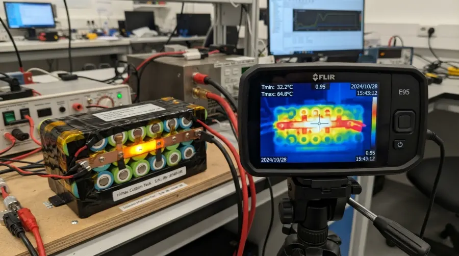
Temperature differences between cells also need to be considered. If cells in different locations operate at different temperatures over extended periods, their performance and aging rates may diverge. Temperature sensor placement should therefore be determined based on thermal test results while also considering sensor response time and installation reliability.
BMS Design: Protection Thresholds Must Work With the Actual Load
BMS design for a custom lithium battery pack should not be based solely on a stated current rating. Battery manufacturers need to evaluate MOSFET losses, current-sense resistor power dissipation, PCB and conductor current-carrying capability, and heat dissipation under actual enclosure conditions.
Protection logic should cover individual series-group overvoltage and undervoltage, charge and discharge overcurrent, short circuit, and abnormal temperatures. TI battery pack reference designs monitor cell voltage, total pack current, cell temperature, and MOSFET temperature, providing a useful technical reference for understanding multidimensional battery protection design.
Overcurrent thresholds and delay times should be defined with reference to actual startup current waveforms. Settings that are too sensitive may interrupt normal equipment startup. Simply increasing the threshold or extending the delay, however, may expose components to currents beyond their design limits.
For equipment with regenerative braking or energy recovery, engineers should also evaluate whether regenerative current at a high state of charge could trigger overvoltage protection and how the equipment will handle returned energy after a protection event.
Prototype Validation and Mass Production: Build Delivery Standards Around Real Operating Conditions
A high-rate lithium battery pack should not be validated using only a single room-temperature discharge test. The test plan should cover critical operating boundaries of the target application and define clear acceptance criteria.
| Validation Test | Primary Parameters to Monitor |
| Continuous-load test | Voltage, runtime, temperature rise, and protection status |
| Repeated peak-current test | Transient voltage drop, hot-spot temperature, and recovery behavior |
| Tests at different states of charge | Startup and output performance at low state of charge |
| Temperature-limit testing | Output capability and derating behavior within the specified operating temperature range |
| Post-aging retest | Changes in capacity, internal resistance, and power output |
| Protection-function testing | Trigger thresholds, delays, and recovery logic |
| Manufacturing consistency checks | Cell-matching records, connection quality, and finished-product electrical parameters |
Protection and abnormal-condition testing should be performed in a test environment with appropriate safeguards. Once prototype validation is complete, critical parameters should be translated into mass-production control requirements, including material traceability, manufacturing records, and end-of-line inspection items.

Defining clear acceptance limits is what turns a claim such as “supports a specified peak current” into a repeatable and verifiable product requirement.
Frequently Asked Questions About Custom High-Rate Lithium Battery Packs
Is a Higher C-Rating Always Better for the Equipment?
Not necessarily. The discharge rate should be selected according to the actual load while also considering voltage sag, temperature rise, capacity, weight, and service life. A C-rating that exceeds the application’s requirements does not necessarily provide a corresponding practical benefit.
Can Peak Discharge Current Be Used as the Continuous Discharge Current?
Not without separate validation. Peak current ratings generally apply to specific durations, intervals, and temperature conditions. Continuous operation requires independent verification that the cells, current path, and thermal design can sustain the required load.
Can Adding More Cells in Parallel Solve Battery Pack Heating Problems?
Under ideal current-sharing conditions and with the same total output current, increasing the number of parallel cells can reduce the current carried by each individual cell. However, connectors, the BMS, busbars, or other components may still develop hot spots, so the entire current path needs to be reviewed.
Does a High-Rate Discharge Battery Also Support High-Current Fast Charging?
Discharge capability does not directly determine charging capability. Charging current should follow the specifications of the selected cells and be designed around temperature, state of charge, the charger, and the BMS charging path. Low-temperature charging, in particular, may require appropriate current limiting or charge-inhibit strategies.
If the Battery Enclosure Does Not Feel Hot, Does That Mean the Internal Temperature Is Normal?
Not necessarily. There may be significant thermal resistance between internal hot spots and the enclosure, and the surface temperature may lag behind changes inside the pack. Properly positioned temperature sensors should be used, and prototype thermal testing should confirm the internal temperature distribution.
What Information Should Be Provided to a Manufacturer for a Custom High-Rate Lithium Battery Pack?
Recommended information includes the equipment voltage range, continuous and peak current waveforms, operating duty cycle, size and weight constraints, ambient temperature, charging method, communication requirements, and service-life targets. If current waveform data is unavailable, measuring the actual equipment load before finalizing the cell and protection design can help establish more accurate requirements.
About Himax Electronics
Himax Electronics specializes in custom battery and power solutions for complex applications worldwide, providing lithium-ion battery packs, power supplies, chargers, and accessories designed to meet specific industry requirements. For high-rate applications, you can provide Himax Electronics with your equipment load profile, operating environment, installation space, and runtime targets to discuss a battery and power solution suited to your project requirements and based on clearly defined operating conditions and verifiable performance criteria.