
Electric Outboard Batteries: Prevent Voltage Drop and Sudden Shutdowns
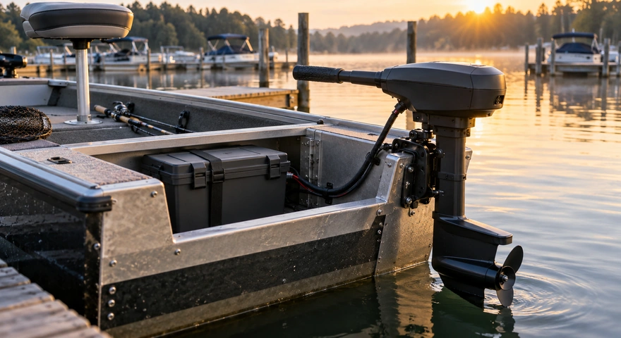
Commercial Summary: HiMAXBATT presents this guide from a battery manufacturing perspective. It outlines practical selection criteria and system integration checks for electric outboard applications, with illustrative calculations rather than product-specific performance guarantees.
Key Takeaways
-
An electric outboard needs a battery that matches the controller’s operating voltage range, actual input power, and communication requirements. Labels such as “48V” or “100Ah” are not enough.
-
Capacity determines how much energy a battery can store. Continuous discharge capability determines whether it can power the outboard reliably. Check these specifications separately.
-
Voltage drop can come from cell internal resistance, cables, and connections. Excessive current or low individual cell voltage can trigger battery management system (BMS) protection and interrupt propulsion.
-
Lithium iron phosphate batteries are one option to evaluate for electric outboards, but suitability depends on pack design, protection settings, and installation conditions.
-
Account for low state of charge, cold weather, sustained heavy loads, salt exposure, and vibration, and reserve enough energy for the return trip.
An electric outboard may run normally at the dock but lose power, reduce output, or shut down unexpectedly once the boat is underway. These problems do not necessarily mean the battery lacks capacity. They can also result from a voltage mismatch, insufficient discharge capability, excessive connection resistance, or poorly coordinated protection settings.
From a battery manufacturing perspective, electric outboard battery selection starts with the entire power system. The cells, BMS, internal conductors, connectors, cables, and motor controller must work together under real operating conditions. This guide explains how to reduce the risk of voltage drop, overcurrent, and unexpected shutdowns.
What Kind of Battery Does an Electric Outboard Need?
A suitable electric outboard battery should continuously deliver the voltage and current the controller requires within its specified temperature and state-of-charge range. Its construction and protection features must also suit the intended marine environment.
Use the following checklist when evaluating a battery:
| Item | Information to Obtain | What to Check |
| Voltage range | Outboard input voltage limits, fully charged battery voltage, and operating discharge range | Fully charged voltage stays within the controller’s input limit, and loaded voltage does not cause premature undervoltage shutdown |
| Continuous discharge capability | Pack continuous current rating and applicable temperature conditions | The battery can support sustained outboard operation and any shared loads |
| Peak discharge capability | Permitted current, duration, and interval between events | Ratings match the controller’s startup and acceleration requirements |
| Battery capacity | Ah, nominal voltage, and Wh or kWh | Capacity covers cruising power, operating time, and reserve energy |
| BMS functions | Cell monitoring, temperature protection, fault history, and reset conditions | Protection works with the propulsion system’s warning and power-reduction strategies |
| Communication compatibility | CAN or other communication requirements and the specified protocol | Interfaces, protocols, and software versions are compatible |
| Marine suitability | Environmental protection, corrosion resistance, mounting, cooling, and installation restrictions | Requirements match the installation location and intended waters |
| Charging compatibility | Charging voltage, current, temperature range, and control method | The charging system follows the battery manufacturer’s requirements |
For outboards that require a proprietary battery or communication authorization, matching voltage alone does not establish third-party battery compatibility.
Are LiFePO4 Batteries Suitable for Electric Outboards?
Lithium iron phosphate (LiFePO4) batteries can be used in electric outboard systems when compatibility has been verified. Their cycling characteristics and thermal stability make them a battery chemistry worth evaluating. However, chemistry is only part of the decision and does not replace a review of complete pack performance.
| Battery Type | Applications to Evaluate | Limitations to Consider |
| Deep-cycle lead-acid | Applications where upfront cost matters and the equipment permits lead-acid batteries | Higher weight; available capacity and terminal voltage may fall noticeably under heavy discharge |
| LiFePO4 | Applications that prioritize repeated cycling, weight, and stable power delivery | Verify cold-weather charging restrictions, BMS current capability, and voltage compatibility |
| NMC lithium-ion | Purpose-built systems with demanding space and weight requirements | Requires appropriate thermal management, structural protection, and system safety engineering |
Two batteries labeled “LiFePO4, 100Ah” may use cells with different discharge ratings, different BMS hardware, and different internal connections. Their continuous output capabilities may differ substantially. Review complete pack specifications rather than relying on chemistry alone.
Voltage Compatibility: Why “48V” Batteries Are Not Automatically Interchangeable
Nominal voltage is not the same as fully charged voltage, nor does it describe actual voltage throughout discharge.
For example, a 16-series LiFePO4 pack has a nominal voltage of 51.2V when calculated at 3.2V per cell. At an upper charging voltage of 3.65V per cell, the pack voltage would be 58.4V. Actual charger settings must follow the battery manufacturer’s instructions. Products marketed as “48V-class” therefore require a closer look at cell count, chemistry, and operating range.
Check at least two voltage boundaries:
Does the fully charged battery stay within the controller’s permitted input range? Does the battery still provide adequate voltage under load at a low state of charge?
If open-circuit voltage looks normal but acceleration triggers undervoltage protection, excessive loaded voltage sag may be the cause. Raising the charging voltage will not fix excessive connection resistance or inadequate discharge capability, and it may create an overcharging risk.
How Do You Calculate the Required Continuous Discharge Current?
If the outboard’s DC input power is known, use this preliminary estimate:
Battery current (A) ≈ DC input power (W) ÷ operating voltage (V)
The following figures are calculation examples, not compatibility specifications for a particular outboard:
| DC Input Power | Operating Voltage | Estimated Current |
| 1,000W | 25.6V | About 39A |
| 3,000W | 51.2V | About 59A |
| 3,000W | 44.8V | About 67A |
| 6,000W | 51.2V | About 117A |
Within an operating range where the controller maintains approximately constant input power, lower voltage means higher current. Calculating current only at nominal voltage may underestimate demand at a low state of charge.
If a product lists shaft output power, account for motor and controller losses rather than treating shaft power as battery input power. Confirm how the manufacturer defines power, and avoid mixing input power, output power, and equivalent horsepower.
Why Can a High-Capacity Battery Still Trip Overcurrent Protection?
Amp-hours describe capacity, not allowable output current.
A 100Ah battery with a 50A continuous discharge rating is not suitable for continuous 100A operation simply because its capacity is 100Ah. Likewise, a BMS labeled “100A” needs clarification: does that number refer to continuous current, short-duration current, or a protection trip threshold?
Pack output capability depends on the cells, BMS, conductive connections, terminals, and cooling conditions. Any one of these can become the limiting factor.
How Can You Reduce Electric Outboard Battery Voltage Drop?
Voltage drop under load can be approximated as:
Voltage drop (V) ≈ current (A) × equivalent resistance (Ω)
This includes resistance inside the battery as well as resistance in external wiring and connections.
For example, if the external supply circuit has a total resistance of 0.01Ω, a 100A current produces about 1V of voltage drop and 100W of resistive heat. This example illustrates the effect of resistance; it is not a cable-sizing standard.
| Source of Voltage Drop | Possible Symptoms | What to Address |
| Elevated battery internal resistance | Battery terminal voltage falls sharply under heavy load | Check cell discharge capability, temperature, aging, and pack load-test results |
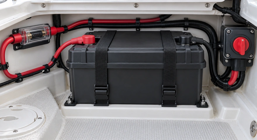
| Excessive cable length or insufficient conductor size | A substantial voltage difference between the battery and controller | Size cables for round-trip length, current, routing conditions, and allowable voltage drop |
| Loose or corroded terminals | Localized heating or intermittent operation | Inspect crimp quality, tightening torque, and corrosion protection |
| Unsuitable switches or connectors | Excessive contact temperature or power loss under load | Verify DC ratings and continuous current capability |
| Increasing cell imbalance | Undervoltage protection trips while the pack still shows remaining charge | Check individual cell voltage differences, capacity variation, and BMS records |
During troubleshooting, compare voltage at the battery terminals and controller input under the same load. A substantial difference points toward the wiring or connections. If battery terminal voltage itself drops sharply, investigate battery condition further.
Cable size should not be selected from power alone or a generic online chart. Ambient temperature, bundled routing, insulation temperature ratings, and terminal capability also matter.
Why Can the BMS Suddenly Shut Down an Electric Outboard?
When the BMS disconnects the output, a protection condition has typically been triggered. The battery is not necessarily empty.
| Protection Type | Possible Causes | Information to Review |
| Cell undervoltage | Low state of charge, voltage sag under high current, or uneven cell capacity | Recorded low cell voltage, load current, and state of charge |
| Discharge overcurrent | Load beyond the permitted range, an obstructed propeller, or abnormal controller input demand | Trip current, delay, and allowable peak duration |
| Temperature protection | Poor compartment cooling, sustained heavy loads, or abnormal ambient temperature | Temperature history, sensor locations, and derating requirements |
| Short-circuit protection | Damaged wiring or a connection fault | Fault location, cable condition, and protection coordination |
| Communication fault | Protocol mismatch, loose connections, or interrupted communication | Fault codes, communication settings, and connection condition |
Reducing unexpected shutdowns requires coordination among controller warnings, power reduction, and BMS protection. Where supported, the controller can warn of low charge and reduce power before normal operation reaches the battery’s hardware protection limits.
Do not bypass the BMS, raise protection thresholds, or repeatedly reset the system to conceal a fault. The BMS also does not replace external short-circuit protection. Fuses, disconnect switches, and circuit protection must be selected for the DC voltage, prospective fault current, and installation requirements.
Some controllers also have input capacitors that draw a brief inrush current when connected to a battery. The battery and outboard manufacturers should confirm whether a precharge circuit is required. A startup protection trip does not automatically indicate insufficient battery capacity.
How Do You Estimate Battery Capacity and Runtime?
Estimate runtime from usable energy and actual average input power:
Estimated runtime (hours) ≈ usable energy (kWh) ÷ average input power (kW)
A 51.2V, 100Ah battery has approximately 5.12kWh of nominal energy. If the operating plan assumes 80% is available for use, that provides about 4.10kWh:
| Average DC Input Power | Calculated Runtime |
| 1kW | About 4.1 hours |
| 2kW | About 2.0 hours |
| 3kW | About 1.4 hours |
The 80% figure is a calculation assumption, not a universal recommendation. Actual usable energy also depends on temperature, aging, protection thresholds, and load. Travel distance further depends on boat weight, hull design, speed, wind, waves, and current.
Plan return-trip reserves around the route and conditions. Battery protection shutdown should not be the planned endpoint of a trip.

What Should You Check for a Marine Battery Installation?
Marine batteries may face moisture, salt spray, vibration, and installation areas where water can collect. An ingress protection rating addresses only part of this environment. It does not establish salt-spray resistance, suitability for prolonged immersion, or the reliability of the entire wiring system.
ISO 23625:2025, Small craft — Lithium-ion batteries, addresses battery selection, installation, and manufacturer-provided safety information. Its scope includes relevant battery systems with capacities greater than 500Wh used for general electrical loads or electric propulsion on small craft. Review applicable requirements for the vessel, intended use, and jurisdiction. Referencing a standard does not establish that a product is certified.
The UK’s Boat Safety Scheme guidance on installed lithium-ion batteries emphasizes using batteries and system components that the manufacturer or supplier declares suitable for the intended marine application, and following installation and operating instructions.
Ask the supplier to clarify:
-
Environmental protection conditions for the enclosure, terminals, and connectors.
-
Battery mounting, permitted orientation, and vibration suitability.
-
Operating and charging temperatures, including cold-weather charging restrictions.
-
Cooling, ventilation, and abnormal-condition response requirements.
-
The exact model, configuration, and test conditions covered by each report.
Electric Outboard Battery FAQ
Can I Use a Car Starter Battery for an Electric Outboard?
The application matters. Starter batteries are designed around brief high-current output, while electric outboards generally require sustained discharge and repeated cycling. Choose a battery with the required continuous output capability based on the equipment specifications, rather than relying on cranking amps alone.
Can a 48V Outboard Use a 51.2V LiFePO4 Battery?
Some systems can, but you must verify the outboard’s input voltage range, fully charged battery voltage, loaded voltage at low charge, and communication requirements. A “48V-class” label alone does not establish compatibility.
Will a Larger Battery Fix Shutdowns During Acceleration?
Not necessarily. If the replacement battery does not provide greater continuous current capability, or the problem involves undersized cables, loose terminals, communication faults, or an obstructed propeller, additional capacity may not solve it.
Why Does the Outboard Stop When the Display Still Shows 30% Charge?
An individual cell may have reached its undervoltage threshold, or overcurrent, temperature, or communication protection may have been triggered. LiFePO4 batteries have a relatively flat voltage curve, so estimating state of charge from voltage alone can be inaccurate. Check battery monitor calibration and BMS records together.
Can I Add Together the Current Ratings of Parallel Batteries?
Not automatically. Parallel capability depends on manufacturer approval, branch resistance, wiring arrangement, and battery condition. If one branch disconnects, the remaining branches may carry more current. Evaluate load sharing under fault conditions as well as normal operation.
Can I Connect Several 12V Lithium Batteries in Series for a Higher-Voltage Outboard?
Consider this only when the battery manufacturer explicitly permits the required series configuration and the protection and charging systems are compatible. An unapproved series connection may exceed the BMS voltage rating and protection design limits.
Can a Waterproof Battery Be Installed Where Water Collects?
Do not decide from a “waterproof” claim alone. Verify the ingress protection test conditions, connector requirements, and manufacturer’s installation restrictions. Also address standing water, corrosion, secure mounting, and maintenance access.
HiMAXBATT: Start With Your Actual Operating Requirements
HiMAXBATT focuses on matching batteries to the equipment they power. When evaluating a HiMAXBATT battery for an electric outboard, provide the outboard model, permitted input voltage, continuous and peak current requirements, target runtime, available installation space, and operating temperatures. Specify any communication requirements as well. Use this information to review the proposed cell configuration, BMS specifications, connections, and validation documents. This creates a clearer basis for battery selection. Compatibility, testing, and supplied configurations are subject to the technical specifications agreed upon by both parties.