
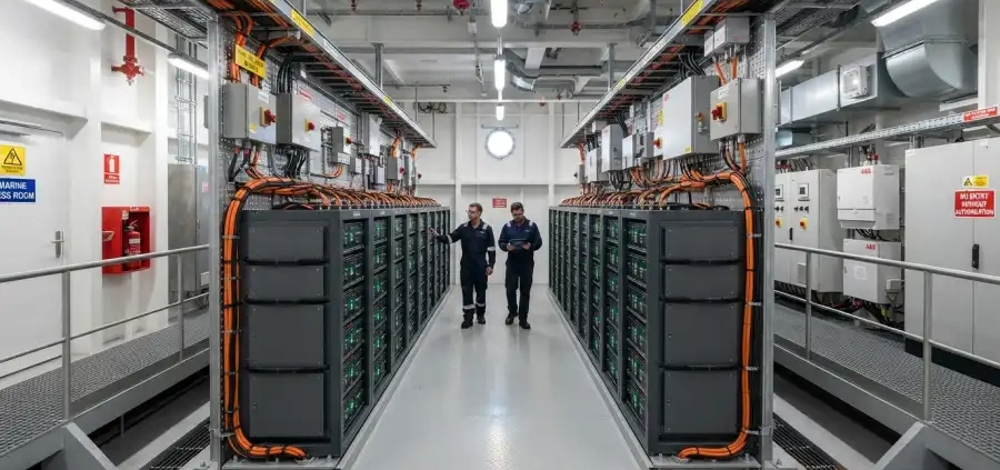
Commercial Disclosure: The HiMASSi® Editorial Team combines local Australian market insight with the battery engineering and manufacturing expertise of Shenzhen Himax Electronics Co., Ltd. to provide practical, technically informed content for businesses, OEMs, system integrators, and industry professionals. As Himax Electronics’ official flagship brand in Australia, HiMASSi® focuses on LiFePO4 batteries, custom battery solutions, BMS technology, charging systems, battery selection, and application-specific power solutions. Our content covers technical guidance, industrial and commercial applications, product updates, and HiMASSi® news. All content reflects HiMASSi®’s official editorial perspective and is intended to help Australian customers evaluate battery solutions based on their application requirements, operating conditions, system compatibility, and project needs.
Key Takeaways
- High-voltage marine battery systems should be incorporated into the overall vessel design during the concept stage, as battery weight, compartment layout, cooling, and maintenance access can all affect vessel arrangement.
- Battery selection must meet both energy and power requirements while accounting for capacity degradation over time, operating temperature, reserve energy, and the vessel’s ability to continue operating after a fault.
- System voltage should be coordinated with propulsion converters, the DC bus, and charging equipment. Equipment should not be selected based only on the battery’s nominal voltage.
- Thermal safety should be addressed in layers across the cell, module, battery cabinet, and battery compartment. It should not rely solely on the battery management system or ventilation equipment.
- Applicable requirements from classification societies, flag-state authorities, and the specific project should be identified early in the design process. Product certification does not replace vessel-level integration review.
Introduction
For electric ferries, hybrid workboats, and other vessels equipped with energy storage systems, batteries are increasingly involved in propulsion, load management, and power control. For shipyards, the challenge has therefore shifted from simply asking “Where should the battery be installed?” to determining “How should the vessel’s space, electrical architecture, and safety functions be designed around the battery system?”
From a battery manufacturing perspective, a high-voltage marine battery system is not simply a collection of battery modules connected in series and installed in a compartment. Cell performance, mechanical structure, protection strategies, and vessel operating conditions are closely interconnected. If any interface is not clearly defined, it can lead to rework later during construction or commissioning.
In this article, “high-voltage battery system” primarily refers to higher-voltage battery systems used for marine propulsion or relatively high-power energy storage. In engineering practice, the commonly used term “high voltage” may not exactly match the voltage classifications defined by applicable marine electrical rules. Each project should therefore clearly define its AC and DC voltage ranges and the corresponding voltage classifications.
- Define the Operating Profile Before Specifying the Battery
The first step in designing a marine battery system is to define what the battery is expected to do: provide all-electric propulsion, support peak shaving in a hybrid system, enable low-emission harbor operation, or supply auxiliary loads. Different applications result in different energy and power requirements.
For example, a short-route ferry may need to focus on dockside charging time and the number of daily cycles. A workboat may place greater emphasis on sudden power changes from thrusters or mission equipment. A hybrid vessel must coordinate power sharing between the battery and onboard generators.
| Design Input | What Needs to Be Defined | Impact on the Battery System |
| Operating Mission | Route length, speed, daily trips, and time at berth | Determines energy demand per mission and cycling intensity |
| Load Profile | Propulsion, thrusters, pumps, and hotel loads | Determines continuous power, peak power, and response requirements |
| Operating Environment | Route temperature, humidity, salt spray, and vibration conditions | Affects cooling, protection, and material selection |
| Energy Replenishment | Shore-power capacity, charging window, and onboard generation capability | Affects charging power and battery capacity sizing |
| Operating Reserve | Delays, detours, and project-specific reserve requirements | Affects the allowable usable energy range |
| Service Life | Operating days per year, cycle count, and maintenance schedule | Affects lifetime targets and replacement planning |
- How Should Marine Battery Capacity Be Calculated?
Capacity determines how long the battery can support the vessel, while power determines how much load it can handle. Both need to be evaluated separately.
An initial estimate can begin with mission energy:
Mission Energy (kWh) = Sum of Power in Each Operating Phase (kW) × Time in That Phase (h)
If the load data is measured downstream of the battery output, the corresponding conversion losses should also be included. Nominal battery capacity can then be estimated as:
Nominal Capacity ≈ Mission Energy ÷ (Power-Path Efficiency × Allowable SOC Window × End-of-Life Capacity Retention)
SOC refers to state of charge. This method is intended for preliminary sizing and does not replace detailed simulation or project-specific safety assessment.
Assume a mission requires 400kWh to be delivered to the loads, with a power-path efficiency of 95%, an allowable SOC window of 80%, and an end-of-life capacity retention of 80%:
400 ÷ (0.95 × 0.8 × 0.8) ≈ 658kWh
These values are assumptions for illustration only and are not universal design standards. The calculation also does not separately include navigation reserve energy. It is also important to confirm whether auxiliary loads such as cooling and ventilation are already included in the mission energy so they are neither omitted nor counted twice.
Once the energy requirement is satisfied, continuous power capability should also be verified at low SOC, low temperature, and end-of-life conditions. A battery system may contain enough total energy while still being unable to continuously supply the required propulsion power.
- System Voltage Must Match the Vessel’s Overall Electrical Architecture
At the same power level, increasing voltage reduces current. For example, ignoring losses, a 500kW load requires approximately 1000A at 500V but only about 500A at 1000V. This can help reduce current requirements for cables and conductive connections, but it also changes insulation, switching equipment, and personnel-protection requirements.
Equipment compatibility should be verified across the battery’s full operating voltage range, including the maximum voltage at full charge, minimum voltage at low SOC, and voltage variation under high-current loads.
Shipyards and system integrators should jointly confirm:
- Whether propulsion converters and chargers can operate across the battery’s full working voltage range.
- Whether DC switches, fuses, and contactors have appropriate ratings and interrupting capacity.
- How pre-charge, bus discharge, insulation monitoring, and maintenance isolation will be implemented.
- How connection conditions, current sharing, and fault isolation will be controlled when multiple battery strings operate in parallel.
- Whether the grounding arrangement and ground-fault response meet applicable design requirements.
DC faults should not be handled using the same assumptions as AC distribution faults. Protection design should account for the fault contribution of the battery, converters, and other power sources, supported by short-circuit analysis and protection-coordination verification.
- Battery Compartment Layout Must Account for Weight, Maintenance, and the Marine Environment
Battery system weight includes more than the cells themselves. It also includes cabinets, support structures, cooling equipment, cables, and associated safety systems. Vessel-level design should therefore use system-level weight and dimensional data.
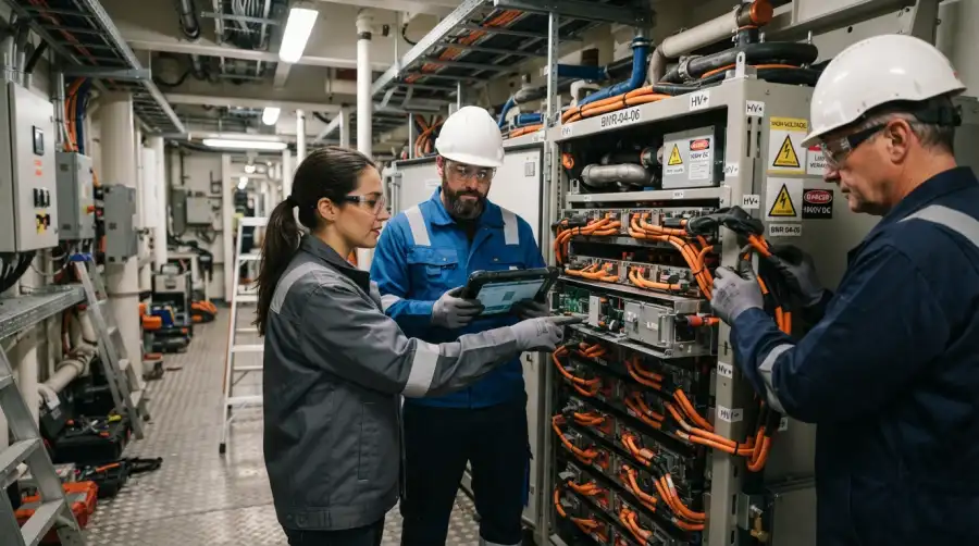
The layout should evaluate how battery weight distribution affects the vessel’s center of gravity, stability, and structural loads while also providing sufficient access for personnel, module removal, and equipment replacement. Providing enough installation space without allowing adequate maintenance access can make future servicing more difficult and increase vessel downtime.
The marine environment also introduces salt spray, moisture, condensation, and continuous vibration. An enclosure’s IP rating only indicates resistance to dust and water under specified test conditions and does not, by itself, demonstrate suitability for long-term marine service.
For liquid-cooled systems, coolant leakage, connection maintenance, and condensation risk should also be evaluated. Lower coolant temperature is not always better. Cooling strategy should consider compartment humidity and dew point.
- Thermal Safety Must Extend from the Cell to the Entire Battery Compartment
The safety design of marine lithium-ion batteries must address both heat generated during normal operation and the risk of thermal runaway under abnormal conditions.
Under normal operating conditions, thermal models should be developed based on charge and discharge current, internal resistance, and ambient conditions. Temperature rise should be evaluated during continuous operation and repeated high-power cycles. Because battery aging can change internal resistance, thermal assessments should also consider aged-battery conditions.
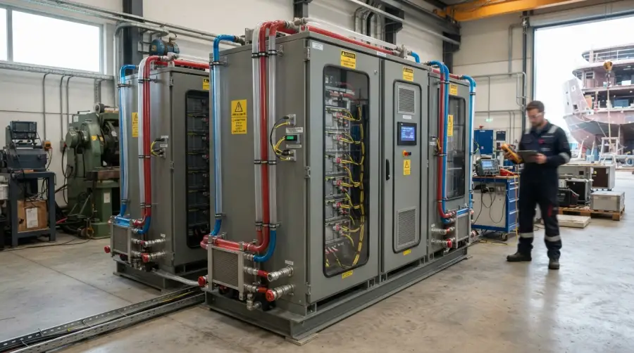
Under abnormal conditions, the relationship among thermal propagation, gas release, detection, isolation, and fire response should be evaluated. DNV’s marine battery safety research notes that when a larger portion of a battery system is involved in an incident, ventilation alone may not be sufficient to control the risk of gas accumulation, making preventive and limiting measures at the battery-design level necessary as well. Reference: DNV Marine Battery Safety Study
| Design Level | Key Areas to Validate |
| Cell and Module | Suitability for intended operating conditions, abnormal behavior, and evidence from thermal propagation testing |
| Battery Cabinet | Temperature monitoring, protective actions, structural design, and gas venting paths |
| Battery Compartment | Ventilation, gas detection, fire protection, and separation from adjacent spaces |
| Vessel-Level System | Alarm coordination, post-fault power availability, and crew response procedures |
Fire suppression media, venting arrangements, and ventilation capacity should be determined based on test data, risk assessment, and applicable rules rather than applying one generic configuration to every battery system.
- Clearly Define the Responsibilities of the BMS, Energy Management, and Vessel Control Systems
The battery management system (BMS) monitors cell and battery conditions and provides information such as allowable charge and discharge power. The vessel’s power management or energy management system coordinates propulsion, generation, and other electrical loads. The protection and control responsibilities of these systems should be clearly separated.
Interface documentation should include more than just the name of the communication protocol. It should also define:
- The meaning of each data point, update rate, and validity criteria.
- How charge and discharge power limits are implemented.
- Responses to communication loss, sensor faults, and invalid data.
- The sequence of alarms, derating, shutdown, and emergency isolation.
- Fault-reset conditions and operator permissions.
Common-mode failure points should also be reviewed. For example, multiple battery strings may appear redundant, but if they all depend on a single cooling system or control-power supply, the actual system redundancy may be lower than the number of battery strings suggests.
- Shore-Charging Conditions Can Influence Vessel Design
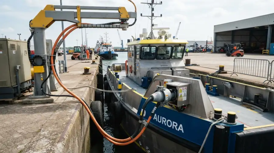
Shore-side charging power should be estimated based on the amount of energy that needs to be replenished and the actual charging window.
For example, if 300kWh must be returned to the battery within 30 minutes, the average battery-side charging power would need to be approximately 600kW. Shore-side input requirements would be higher once charging losses and simultaneous onboard loads are considered.
However, this does not mean the battery can accept that power throughout the entire charging process. SOC, temperature, cell condition, and charging strategy can all cause charging power to decrease. Turnaround time should therefore be validated using the actual charging curve, while allowing time for berthing, connection, inspection, and disconnection.
If shore-side power capacity is insufficient, the vessel’s operating profile, onboard battery capacity, and charging schedule should be reconsidered together rather than simply increasing the charger’s rated power.
- Define Review Documentation and the Validation Plan Before Construction
During the early design stage, the shipyard should work with the vessel owner, battery manufacturer, system integrator, and relevant approval authorities to identify applicable requirements and clearly define responsibilities.
ABS publishes dedicated requirements for lithium-ion battery applications in marine and offshore industries, which can serve as a reference for understanding typical review considerations. Each project must still confirm the actual applicable rule version and approval conditions. Reference: ABS Requirements for Use of Lithium-Ion Batteries in the Marine and Offshore Industries, 2024
The delivery plan should identify required design calculations, test reports, control-interface documents, and maintenance information, along with factory acceptance testing, onboard commissioning, and sea-trial validation. Verification should cover more than normal charging and discharging. It should also include scenarios such as communication loss, cooling failure, power limiting, and isolation actions.
Frequently Asked Questions (FAQ)
Is a Higher Voltage Always Better for a Marine High-Voltage Battery System?
No. Increasing voltage reduces current at the same power level, but it also changes equipment selection, insulation, and protection requirements. System voltage should be determined based on propulsion power, cable routing, converter specifications, and maintenance conditions.
Are LiFePO4 Batteries Suitable for Every Electric Vessel?
Not necessarily. Battery chemistry should be selected by comparing energy density, power capability, temperature characteristics, service life, and system-level test data. Choosing a particular chemistry does not eliminate the need for thermal propagation and fire-safety design.
If the Battery Has Type Approval, Is Vessel-Level Review Still Required?
Yes. Integration review is still required according to the project’s applicable requirements. Type approval generally applies to a specific product and defined conditions of use. It does not automatically cover the battery compartment layout, electrical protection, cooling system, or control interfaces of a particular vessel.
Can the BMS Replace High-Voltage Distribution Protection?
No. The BMS monitors and manages battery conditions, while high-voltage distribution protection requires appropriately rated switching, fusing, isolation, and monitoring devices. These systems must work together in a coordinated manner.
Can the Battery System Also Serve as the Vessel’s Emergency Power Source?
This requires a dedicated assessment. Whether dual use is permitted depends on applicable rules, required independence, installation location, required supply duration, and common-mode failure risks. Remaining battery capacity alone is not sufficient to determine suitability.
What Information Should a Shipyard Prepare Before Requesting a Quote from a Battery Manufacturer?
Recommended information includes the vessel type, operating profile, load curve, operating voltage range, available compartment space, environmental conditions, charging window, service-life targets, and applicable approval requirements. The more complete the information, the easier it is to develop a technically verifiable solution.
About Himax Electronics
Himax Electronics specializes in custom battery and power solutions for complex applications worldwide and provides application-specific lithium-ion battery packs, power supplies, chargers, and accessories for a range of industry requirements. For marine projects, customers are welcome to provide operating profiles, electrical interfaces, installation conditions, and applicable certification requirements to discuss battery and power-system compatibility with Himax Electronics.
Final product capabilities, test scope, and project suitability should be based on mutually confirmed technical specifications and validation documentation.