What Every Hardware Engineer Should Know Before Specifying a Cell
By Joan, Battery Engineer — Custom Pack Development | Himax Electronics | himaxelectronics.com
A Note from the Bench
I review a lot of custom battery specifications.In fact, the single most common mistake I see from embedded hardware engineers is not a chemistry error or a capacity miscalculation — rather, it is a mismatch between the battery’s BMS protection profile and the actual load behavior of the MCU-centric board it is supposed to power do not match.
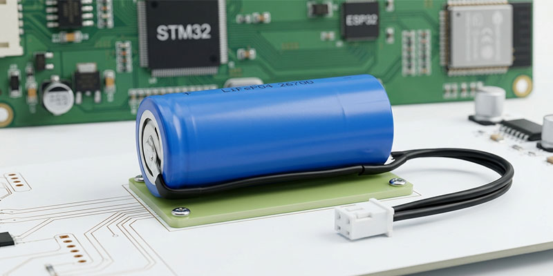
This article is about a real project spec I recently worked through: a single-cell LiFePO4 pack at 3.2V nominal, 4000mAh, designed to power a circuit board assembly built around an STM32 core MCU, an ESP32 wireless hub IC, a WS2812 RGB status LED, and a set of peripheral sensors. The application region is Australia; the form factor is constrained; the BMS requirements are non-negotiable.
If you are an OEM hardware developer, a product manager at an IoT company, or a firmware engineer who suddenly finds yourself responsible for battery selection — this post is written for you. I will walk through the complete specification, explain why each parameter was chosen, and flag the real engineering tradeoffs that do not show up in typical datasheets.
Why LiFePO4 for an MCU-Centric Board?
Why LiFePO4 for an MCU-Centric Board? When engineers ask me to recommend a battery chemistry for an STM32 + ESP32 based product, LiFePO4 is almost always my first recommendation — and here is why. Specifically, three key advantages make it stand out.
-
Flat Discharge Voltage Is a Feature, Not a Limitation
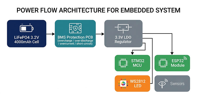
STM32 MCUs typically operate from a regulated 3.3V rail derived from the battery. Similarly, ESP32 modules also run at 3.3V, though they draw significantly more current during Wi-Fi or BLE transmission bursts. A LFP cell delivers a stable ~3.2V across roughly 90% of its capacity, which means your LDO or DC-DC converter operates within its optimal efficiency range for the vast majority of the battery’s usable life.
Contrast this with a Li-ion NMC or LCO cell, which starts at 4.2V fully charged and sags to 3.0V at cutoff. The wide swing forces your power supply design to accommodate a 40% input voltage range — increasing component count, BOM cost, and efficiency penalties at both ends.
-
Safe Chemistry for Enclosed PCB Environments
Your battery will likely live inside a plastic or metal enclosure, often without forced ventilation. LFP’s thermal stability — the olivine phosphate crystal structure does not release oxygen under abuse conditions — makes it the safest lithium chemistry for embedded product designs. Consequently, it is ideal for enclosed environments without forced ventilation. In fifteen years of battery engineering, I have never seen a LFP cell in thermal runaway from a BMS fault. The same cannot be said for NMC.
-
Cycle Life Aligns with Product Lifecycle
A well-managed LFP cell cycled to 80% depth of discharge delivers 2,000–3,000 full cycles. For example, at one full charge/discharge cycle per day, that is over 5 years — and that typically exceeds the product lifecycle for most IoT devices. Your customer will not need a battery replacement within the warranty period.
| From my workbench: I have seen ESP32-based sensor products destroy NMC cells in 18 months because the ESP32 Wi-Fi transmission spikes — which can reach 500mA–600mA for 100–200ms — hammer the cell at elevated current per unit capacity. LFP handles these spikes gracefully. The C-rate math matters: a 4000mAh cell at 500mA peak draw is only 0.125C. LFP is comfortable at up to 1C continuous and higher for brief bursts. |
Full Technical Specification: Himax LiFePO4 3.2V 4000mAh Pack
Below is the complete specification for this custom pack configuration (Order Reference: 3155, manufactured for Solaflo by Himax Electronics):
| Pack Model / Label | LiFePO4 Battery 3.2V 4000mAh 12.8Wh | Model: 32-4BP |
| Nominal Voltage | 3.2 V |
| Nominal Capacity | 4000 mAh (12.8 Wh) |
| Cell Configuration | 1S1P (single cell) |
| Cell Model | LFP 26700 3.2V 4000mAh |
| BMS Protection | Included — overcharge, over-discharge, overcurrent, short-circuit |
| Max Charge Current | 1.0 A |
| Max Continuous Discharge | 60 mA (matched to board average load) |
| Wire Gauge | Rated for 1.5 A — per customer requirement |
| Lead Length | 150 mm (connector not included in length) |
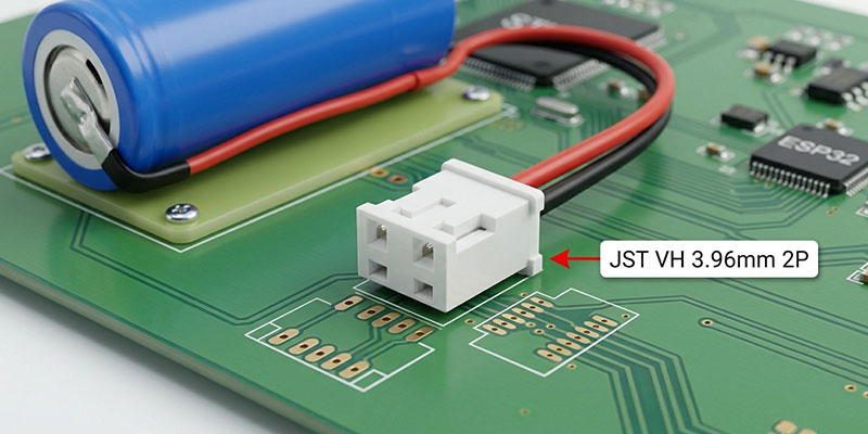
| Connector | JST VH 3.96mm Pitch 2P Female — wire sequence per drawing |
| Max Dimensions | 27.5 × 26.8 × 76 mm |
| Enclosure | Blue PVC wrap |
| Cell Support Frame | None required |
| Waterproofing | None (device enclosure handles IP rating) |
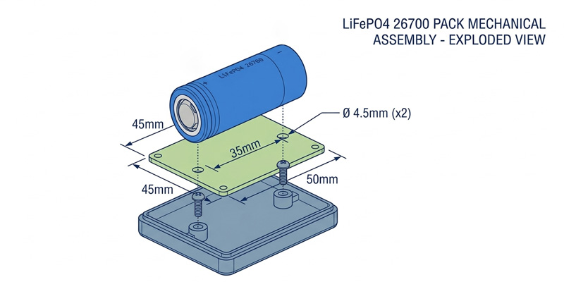
| Mounting Plate | Epoxy PCB fixture: L45 × W50 mm, hole diameter 4.5 mm, hole spacing 35 mm |
| Label Content | Nominal V, capacity, charge/discharge limits, date code, manufacturer |
| Date Code | SEP 2025 (sample order) |
| Application Region | Australia |
| Target Load | STM32 MCU + ESP32 + WS2812 LED + peripheral sensors |
| Packaging | Insulated wrap, cardboard carton, no UN certification required |
| Shipping | DHL express |
Why JST VH 3.96mm? A Connector Choice Rationale
We did not select the JST VH 3.96mm 2P female connector arbitrarily. To elaborate, here is the engineering reasoning behind it, which I walk through with most OEM clients:
- Current rating: The VH series carries a 10A rating, far exceeding the 1.5A wire gauge requirement. This gives robust mechanical and electrical margin.
- Pitch: 3.96mm pitch is large enough to handle cleanly in field assembly without risk of mis-insertion, unlike 2.00mm or 2.54mm JST PH/XH alternatives.
- Locking: The VH series uses a positive latch. For a product that may be assembled and disassembled during manufacturing QC, rework, or end-user battery replacement, a secure mechanical lock prevents accidental disconnection.
- Wire sequence: Confirm with your PCB layout engineer that the polarity convention on your board matches the Himax wiring. We follow the customer-supplied drawing — but verify before layout is finalized. A reversed VH connector will destroy your MCU.
| Engineering tip: If your PCB is still in layout review, ask your Himax contact for the exact connector footprint and mating plug part number. Designing the through-hole pad size correctly for a VH 3.96mm female connector avoids a respin. Most layout errors I see come from engineers copy-pasting a PH 2.0mm footprint by mistake. |
Load Analysis: STM32 + ESP32 + WS2812 + Sensors
Let me run through the power budget for the target application. This is the kind of analysis I do for every OEM client at the start of a battery selection discussion, because the ‘right’ capacity depends entirely on duty cycle.
| Load Component | Typical Current | Duty Cycle | Avg Contribution |
| STM32 MCU (active) | 10–30 mA | ~20% | ~4–6 mA |
| STM32 MCU (sleep) | 1–10 µA | ~80% | Negligible |
| ESP32 (Wi-Fi TX burst) | 150–600 mA | <0.5% | ~1–3 mA avg |
| ESP32 (idle / modem sleep) | 3–20 mA | ~15% | ~0.5–3 mA |
| WS2812 LED (on, mid brightness) | 20–60 mA | <5% | ~1–3 mA avg |
| Peripheral sensors | 1–15 mA | ~10% | ~0.1–1.5 mA avg |
| Total average draw (estimated) | — | — | ~10–20 mA typical |
At 10–20 mA average draw, a 4000mAh LFP cell provides 200–400 hours (8–16 days) of runtime without any charging. With a 1A solar charge input and typical Australian solar irradiance, this system can run indefinitely in most deployment environments.
We specify a conservative maximum continuous discharge rating of 60 mA (from the order form) — it reflects the average peak, not worst-case burst. We set the BMS overcurrent cutoff above the ESP32’s Wi-Fi burst envelope to avoid nuisance trips during normal operation. This is a BMS tuning decision I make for every client based on their MCU’s actual current profile.
BMS Design: The Four Protections You Cannot Omit
The order specification calls for a protection board with four core functions. Here is what each one protects against in the context of an MCU board load:
Overcharge Protection
LFP charge cutoff is 3.65V per cell. If the charger malfunctions or is incorrectly set, the BMS disconnects the charge FET before the cell reaches a damaging voltage. For a 1A charge current into a 4Ah cell (0.25C rate), this is not a common failure mode — but it is still a mandatory protection for a certified product.
Over-Discharge Protection
LFP deep discharge cutoff is typically 2.5V. Below this threshold, copper dissolution at the anode can permanently damage the cell. With an STM32 + ESP32 combination, firmware bugs that prevent deep sleep — a common issue during development — can drain a cell faster than expected. The BMS is the last line of defense.
Overcurrent Protection
Set to protect against sustained currents exceeding the cell’s safe discharge rate. For this application, the overcurrent threshold is tuned above the ESP32 Wi-Fi burst (up to ~600mA) to prevent false trips, while still protecting against dead shorts from assembly errors.
Short-Circuit Protection
Activates within microseconds of a dead short. This is particularly relevant during PCB assembly and debug — a solder bridge or dropped screwdriver across the supply rails will not destroy the cell or start a fire. The BMS disconnects and waits for the short to clear.
| My recommendation: Always request a BMS with separate charge and discharge FETs (two-FET topology). This allows the system to charge via solar while simultaneously powering the load — which is the normal operating mode for a solar-assisted IoT node. A single-FET BMS cannot do this simultaneously. |
The Epoxy Mounting Plate: Mechanical Integration Done Right
This specification includes a custom epoxy PCB mounting plate (L45 × W50 mm, 4.5mm hole diameter, 35mm hole spacing). This detail is worth explaining, because it often surprises engineers who have only worked with off-the-shelf battery packs.
The mounting plate serves three functions:
- Mechanical restraint: It prevents the cell from shifting inside the product enclosure under vibration or drop shock — a key requirement for devices shipped to remote field locations.
- Thermal coupling: The epoxy board acts as a mild thermal spreader, reducing hotspot concentration at the cell terminals during charge/discharge cycling.
- Assembly repeatability: Standardized hole spacing (35mm between centers) allows automated screw-driving in volume production, reducing assembly labor cost.
The 4.5mm hole diameter accommodates M4 hardware with washers, which is a standard size for ABS and polycarbonate enclosure bosses used in Australian-market consumer electronics.
Ordering & Customization at Himax Electronics
The 3.2V 4000mAh LFP pack described here is available through Himax Electronics as a standard OEM product or fully custom configuration. Key options available for your project:
- BMS threshold tuning: Overcurrent, over-discharge, and temperature cutoff parameters can be adjusted to match your specific load profile.
- Connector options: JST VH, JST PH, Molex Micro-Fit, bare wire, or custom connector. Specify female/male and wire sequence.
- Lead length: Standard 150mm or custom length. Wire gauge specified to current requirement.
- Mounting hardware: Epoxy plate, plastic brackets, or foam adhesive — all available with custom dimensions.
- Labeling: Custom brand label, regulatory markings (CE, UL, RCM for Australia), or private-label.
- Volume: From prototype sample quantities to mass production with full QC documentation.
Full IoT battery portfolio: himaxelectronics.com/iot-battery/
Product page — LiFePO4 3.2V 4000mAh: himaxelectronics.com/product-item/lifepo4-battery-3-2v-4000mah/
Request a quote or technical consultation: himaxelectronics.com/contact/
Final Thoughts from the Bench
Every battery I spec starts with the same question: what does this board actually do, hour by hour, across its real operating day? The LFP 3.2V 4000mAh pack described in this article is a precise match for an STM32 + ESP32 + WS2812 system because the chemistry, the BMS tuning, the connector, and the mounting fixture were all chosen together — not as separate decisions by separate people.
If you send me a board schematic and a duty cycle estimate, I can turn around a battery specification and power budget analysis in one working day. That is the kind of collaboration that prevents expensive product revisions after your PCB is already in production.
Get in touch with the Himax Electronics team. We work from the cell chemistry up — and we do not stop until the battery fits your product as precisely as any other designed component.