Tag Archive for: Custom Li-Ion Battery Packs

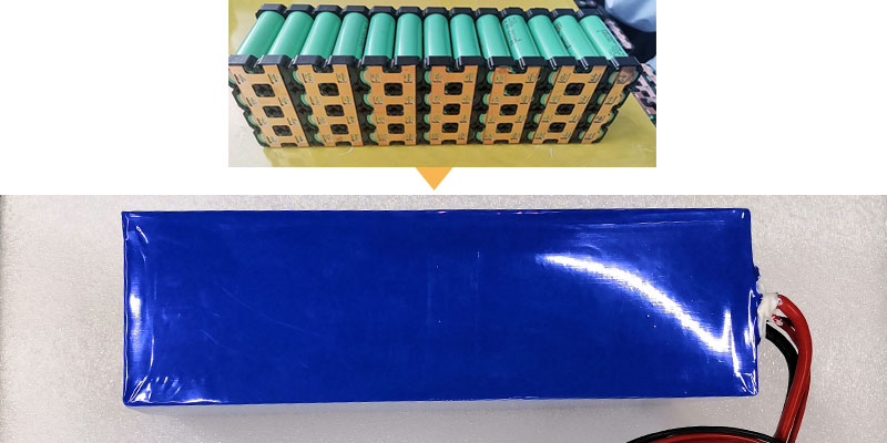
Himax Electronics 25.2V 2000mAh 7S1P Li-ion battery pack with integrated BMS for portable medical device

By  Dawn  •  Battery Engineer, Safety & Compliance  •  Himax Electronics  •  July 2026

Topics: Medical Battery Pack  /  Li-ion Safety  /  BMS  /  IEC 62133  /  Custom Pack Development


Designing a medical device battery pack 25.2V requires more than just picking cells and wiring them together. When a medical device team reaches out about a custom battery, the first question they ask is usually about voltage or capacity. The second is usually about size. By the third conversation, the question that actually matters surfaces: “What does certification require, and how does that impact our timeline?”

However, that shift in concern is entirely predictable, and it’s the one I prepare for in every medical battery development engagement. Certification is not a step that happens after the battery is designed. It’s a constraint that shapes the design from the first component selection. Get it wrong early and you’re doing a redesign at the worst possible time — when the device team is already pressure-testing their regulatory submission schedule.

This post is about what it actually takes to design a 25.2V 2000mAh lithium-ion battery pack for a portable medical device correctly. I’ll cover the configuration rationale, the BMS requirements that are specific to medical applications, the certification landscape, the pass-through charging question that comes up in almost every portable medical device project, and the physical design constraints that make this category different from industrial or consumer battery work.

I’m writing this for engineers and product managers at medical device companies who are in the early-to-mid stage of a battery development conversation and want to understand what they’re getting into before committing to a supplier.


Why 25.2V? The Voltage Architecture of a 7S1P Li-ion Pack

A 25.2V nominal voltage in a lithium-ion pack means seven cells in series (7S). Each standard lithium-ion 18650 cell, for instance, has a nominal voltage of 3.6V, and 7 × 3.6V = 25.2V. The full-charge voltage is 4.2V per cell, giving a pack charge voltage of 29.4V. We typically set the discharge cutoff at 3.0V per cell, giving a pack cutoff of 21.0V. This is the operating window your device’s electronics need to accommodate.

The 1P in 7S1P means a single cell per parallel group — one cell at each of the seven series positions. This gives a pack capacity equal to the capacity of a single cell: 2000mAh (using 18650 cells with 2000mAh rated capacity). The total energy is 50.4Wh (25.2V × 2.0Ah), which falls within the 20–40Wh range that’s common for portable medical devices in the 24V system class.
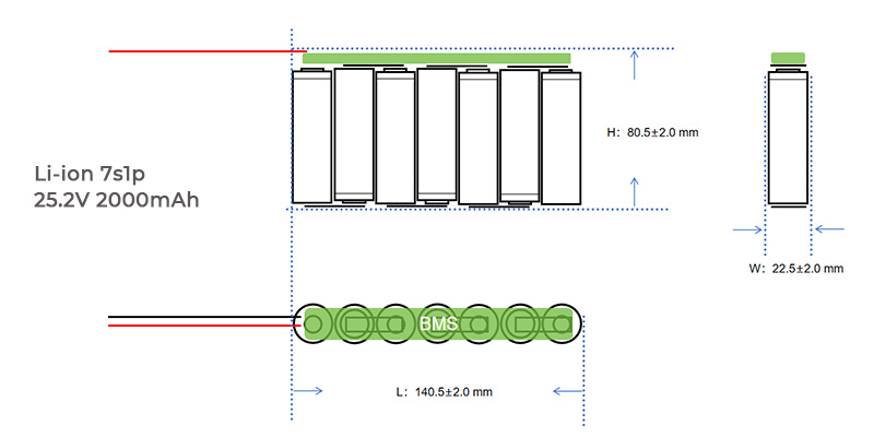
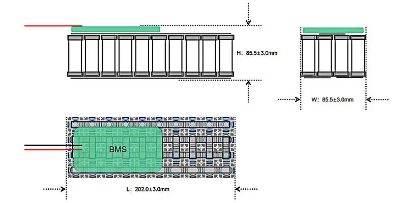
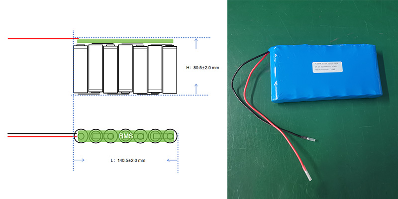
Layout diagram of Himax Electronics 25.2V 7S1P 18650 Li-ion medical battery pack showing BMS and dimensions 140.5x22.5x80.5mm

Why Not a Higher-Capacity Cell?

A natural follow-up question is why use a 2000mAh cell rather than a 3000mAh or 3400mAh cell, which are also available in 18650 format. The answer for medical applications comes down to two factors: validated performance data and certification traceability.

Higher-capacity 18650 cells are optimized for energy density, which sometimes comes at the cost of discharge rate capability and cycle life consistency. A 2000mAh cell in a medical application where the continuous discharge current is 2.0A (1C rate) is operating at a moderate, well-characterized load. The same cell at 2.0A discharge with a 3400mAh cell would be at 0.59C — which sounds better, but the cell selection should be driven by the actual load profile and certification history, not simply by maximizing capacity. In medical development, a well-documented cell with a clean safety and certification record is worth more than an extra 400mAh.

Pack Dimensions and Physical Constraints

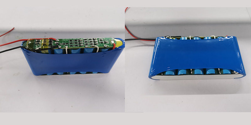
The preliminary configuration for a 7S1P 18650 pack in this class produces a pack with approximate dimensions of 140.5 × 22.5 × 80.5mm (±2.0mm) and a weight of approximately 350g. The layout positions the seven cells side by side in a single row, with the BMS board running along the base of the cell array.


Figure 1: 7S1P 18650 pack layout — L: 140.5±2.0mm × W: 22.5±2.0mm × H: 80.5±2.0mm. BMS board positioned along the cell base.

However, a few things to note about these dimensions for device integration:

  • 5mm width is narrow enough to fit in a grip area or a handle cavity on most briefcase-format portable instruments.
  • 5mm length is close to the length of a standard AA battery holder × 7 — which gives an intuitive sense of the longitudinal footprint inside a device housing.
  • 5mm height is the dimension most often negotiated in custom pack development: if device housing height is constrained, the cell orientation or BMS placement can be adjusted to reduce this dimension, with a corresponding increase in length or width.
  • 350g weight is meaningful in a portable device context. If the total device target weight is under 2kg, the battery represents roughly 17–18% of the budget — which is typical and reasonable for this energy class.


Consequently, these dimensions are a preliminary starting point, not a constraint. Custom battery development for medical devices almost always involves iterating the physical design alongside the device housing design. The cell chemistry, voltage, and capacity are fixed by the 7S1P 18650 configuration; the physical arrangement of those cells and the BMS can be adapted to whatever 3D envelope the device team specifies.

The BMS: What “Integrated Smart BMS” Actually Means in a Medical Context

Every battery supplier will tell you their pack includes a BMS. In medical device applications, what the BMS does — and how it communicates with the device — matters considerably more than in consumer or industrial applications. Let me break down what a well-specified BMS looks like for this application.

Protection Functions

These are the baseline safety functions that any BMS in a medical battery must include:

  • Overcharge protection: disconnects the charge path if any cell reaches 4.25–4.28V, preventing lithium plating and thermal events during charging
  • Over-discharge protection: disconnects the discharge path if any cell drops below 2.5–3.0V, preventing irreversible capacity loss and cell damage
  • Overcurrent protection: limits discharge current to the rated maximum (2.0A continuous, 6.0A peak ≤1 second for this configuration) and disconnects on fault
  • Short-circuit protection: hardware-level cutoff in microseconds on external short circuit detection
  • Temperature protection: thermistor monitoring with charge inhibit below 0°C and above 45°C, discharge inhibit at temperature extremes. Critical in medical applications where the battery may be near a patient or in a heated enclosure
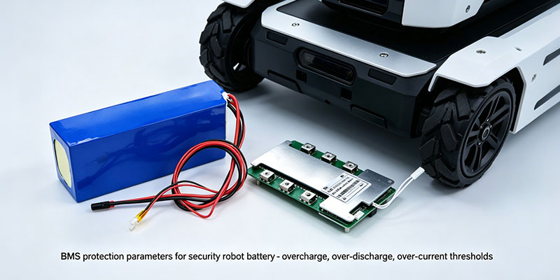
Smart BMS protection functions for medical device Li-ion battery: overcharge, over-discharge, temperature, SMBus communication

Communication Interface: SMBus, UART, or I2C

Standard consumer battery BMS designs have no communication interface — they protect and that’s all. Medical devices almost always need more. The device firmware needs to know:

  • Remaining capacity (state of charge as a percentage or mAh remaining)
  • State of health (capacity relative to original rated capacity)
  • Current pack voltage and cell-level voltages (for imbalance detection)
  • Temperature
  • Fault status and error codes
  • Cycle count


These data are surfaced through a communication bus — SMBus (the most common in medical devices), UART, or I2C depending on the device controller architecture. SMBus is based on the Smart Battery Specification (SBS), which defines a standard register set that many medical device firmware teams already have drivers for. If your device uses an SMBus fuel gauge, specifying SMBus compatibility at the battery level is the path of least integration friction.

Design note from the field:


One of the most common integration problems I see in medical battery projects is a mismatch between

the BMS communication protocol and what the device firmware team assumed. “Smart BMS” on a spec

sheet could mean SMBus, UART, I2C, or a proprietary protocol. Specify the protocol and register

map you need before the prototype is built — retrofitting the communication interface adds

weeks to the development schedule.


Pass-Through Charging: Operating While Connected to External Power

This is the requirement that comes up in nearly every portable medical device project and generates the most confusion: the device must be able to operate while connected to external power, and the battery must support this without degradation.

In battery engineering, this is called pass-through charging or power path management. The behavior is: when external power (the charger) is connected, the device draws power from the charger — not the battery. The battery charges in the background. When external power is removed, the device transitions seamlessly to battery power.

Implementing this correctly requires either:

  • A power path management IC on the device board (preferred for precise control) that handles the charger-to-battery switchover — not a battery-level feature, but a device-level design
  • A BMS with integrated pass-through support (less common, but available) where the BMS manages both the charge and load paths simultaneously with minimal voltage transient on switchover


Specifically, the key concern in medical applications is what happens to device operation during the switchover. A brief voltage dip during the transition from charger to battery can cause microcontroller resets or sensor glitches in sensitive medical electronics. Switchover time and voltage transient specs should be defined as part of the battery-device interface requirements, not assumed.

Certification: The Standards That Matter and What They Actually Test

Unsurprisingly, this is where I spend the most time in early medical battery development conversations, because it’s the area where misconceptions are most costly. Let me go through the relevant standards and what each one actually requires.

UN38.3 — Transport Safety

UN38.3 is a transport certification, not a product safety certification. It certifies that lithium-ion cells and batteries are safe to transport by air, sea, and road. The test protocol includes: altitude simulation, thermal cycling, vibration, shock, external short circuit, impact/crush, overcharge, and forced discharge. The battery pack and its cells must pass all eight tests for most configurations.

UN38.3 is required by law for any shipment of lithium-ion batteries by air or sea. It’s not optional if you’re importing or exporting your device. But it’s not a medical device safety standard — it doesn’t evaluate the battery’s performance in service or its compatibility with medical device requirements. Think of it as the floor, not the ceiling.

IEC 62133 — Battery Safety for Portable Applications

IEC 62133 is the product safety standard for rechargeable battery cells and packs used in portable applications. It covers electrical and mechanical safety tests including continuous charge, abnormal charge, forced discharge, external short circuit, free fall, mechanical shock, vibration, and thermal abuse. The standard has two parts: Part 1 for Ni-MH and Part 2 for lithium systems (which is what applies here).

IEC 62133-2 certification is commonly required by retailers and importers for lithium-ion products sold in Europe, North America, and Asia-Pacific. For medical devices, it’s often a prerequisite for the device-level regulatory submission because it provides independent third-party evidence that the battery has been tested to a recognized safety standard.

One important clarification: IEC 62133 certifies the battery as a component, not the device as a system. If your device regulatory pathway requires a system-level battery safety evaluation (which some medical device categories do), IEC 62133 certification of the battery component supports but does not replace that evaluation.

IEC 62619 — For Industrial and Higher-Power Applications

IEC 62619 is relevant if your device falls into a higher-power or stationary/semi-stationary category. For a 25.2V 2000mAh portable device with a maximum 2A continuous discharge, IEC 62133-2 is typically the applicable standard. IEC 62619 covers secondary lithium cells in industrial applications and becomes relevant when the pack power is above the IEC 62133 scope, or when the device is classified as industrial rather than consumer/portable.

CE Marking for Medical Devices (EU MDR 2017/745)

If your device is sold in the EU, the battery pack needs to be addressed in your device’s technical documentation under the EU Medical Device Regulation (MDR 2017/745). The battery is a critical electrical subsystem, and the MDR requires demonstration that it meets the General Safety and Performance Requirements (GSPR) of Annex I.

In practice, this means the battery supplier needs to provide: a declaration of conformity, the applicable test reports (UN38.3, IEC 62133), traceability documentation for the cells used, and a MSDS/SDS for the battery. The device manufacturer incorporates this documentation into their technical file.

Certification checklist for a 25.2V 2000mAh medical battery pack (EU market):


•  UN38.3 — required for transport (cell-level and pack-level)

•  IEC 62133-2 — product safety standard for lithium-ion portable batteries

•  CE Declaration of Conformity — for devices placed on the EU market

•  MSDS / SDS — material safety data sheet for the battery pack

•  Traceability documentation — cell manufacturer, batch, test reports

•  Optional: IEC 62619 if device classification requires it

•  Optional: UL 2054 or UL 1642 for US market (UL listing, not always mandatory

for Class II medical devices but increasingly expected by hospital buyers)


The Development Process: From Inquiry to Certified Sample

In practice, medical device teams often underestimate how long the battery development and certification path takes. Here is an honest timeline overview based on the development stages for a custom pack in this class:

Phase 1: Requirements Finalization (2–4 weeks)

This is the stage where the device team shares mechanical CAD, power consumption data, thermal environment specs, and communication protocol requirements. Most medical projects also execute an NDA at this stage — a standard practice that a reputable battery supplier will accommodate without friction. Ultimately, the output of this phase is a locked technical specification for the battery.

Phase 2: Prototype Development (4–8 weeks)

The battery pack prototype is built and validated against the spec. This includes electrical performance testing (capacity, discharge curves, protection function verification), dimensional verification, and BMS communication testing. Typically 3–5 prototypes are produced for the device team to evaluate in actual device hardware.

Phase 3: Design Iteration (2–6 weeks, if needed)

Physical fit adjustments, connector changes, and BMS firmware tuning happen here. For medical applications, changes at this stage need to be documented because they affect the certification test object. Changes after certification testing restart the test process for affected tests. This is the stage-gate discipline that medical battery development requires.

Phase 4: Certification Testing (8–16 weeks)

UN38.3 and IEC 62133 testing are conducted at an accredited third-party laboratory. UN38.3 typically takes 4–6 weeks. IEC 62133 takes 6–10 weeks. These can be run in parallel if the test lab schedule allows. No configuration changes should occur during the test period; any change requires re-test of the affected protocols.

Phase 5: Production Qualification and Supply (4–8 weeks after certification)

First production batch is built, inspected, and released. For medical device OEM customers, this typically includes a First Article Inspection (FAI) and agreement on ongoing incoming inspection criteria.


Total timeline from first technical conversation to certified production sample: typically 6 to 9 months. Device teams that start the battery development conversation early — before the mechanical design is locked — consistently have better outcomes than those who treat the battery as a late-stage procurement item.

Full Specification Reference


Parameter Specification
Cell Li-ion 18650, 2000mAh, 3.6V nominal
Configuration 7S1P
Nominal Voltage 25.2V
Rated Capacity 2000mAh
Energy 50.4Wh
Charge Voltage 29.4V
Charge Method CC/CV
Charge Current 0.5C–1.0C (1.0–2.0A)
Discharge Cut-off Voltage 21.0V
Max Continuous Discharge 2.0A
Peak Discharge (instant) 6.0A (≤1 second)
BMS Protection Overcharge, over-discharge, overcurrent, short-circuit, temperature
BMS Communication SMBus / UART / I2C (specify at inquiry stage)
Pass-through Charging Supported (power path management required at device level)
Dimensions (preliminary) L 140.5±2.0mm × W 22.5±2.0mm × H 80.5±2.0mm
Weight (approx.) 350g
Certifications UN38.3, IEC 62133-2, CE DoC (others on request)
Customizable Dimensions, connector, BMS comms protocol, labeling, enclosure

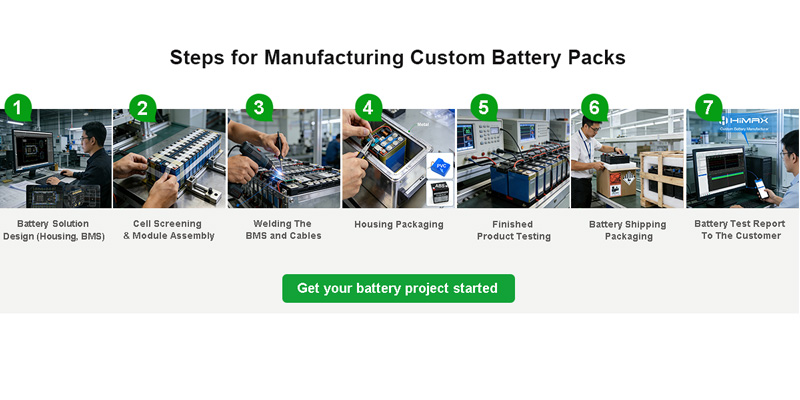
IEC 62133 and UN38.3 safety certification testing process for Himax Electronics portable medical device battery pack

What to Look for in a Medical Battery Supplier

I’m going to be direct here because I think the industry often avoids this conversation. Not every battery supplier is set up to support a medical device development project well. Here are the things that actually matter when evaluating a supplier for a medical battery:


  • Cell traceability:

  • the supplier should be able to provide documentation identifying the cell manufacturer, model, production lot, and test data for every batch. We cannot accept generic cells from undocumented sources in medical applications where traceability is a regulatory requirement.

  • Certification documentation readiness:

  • 3 and IEC 62133 test reports should be available on request for standard configurations, and the supplier should have experience managing third-party lab submissions for custom packs.

  • NDA process:

  • a supplier that hesitates or creates friction around executing an NDA before technical discussions is not a good fit for a medical product development environment. Confidentiality is standard in this industry.

  • Engineering responsiveness at the proposal stage:

  • the quality of the preliminary technical response tells you a lot about what the design process will look like. A supplier who can turn around a well-reasoned preliminary configuration — with dimensions, BMS specs, charge/discharge parameters, and certification pathway comments — has the technical depth the project needs.

  • Customization capability:

  • medical devices rarely fit a standard battery configuration. The supplier needs to be able to adjust dimensions, BMS firmware, communication protocol, and mechanical integration without treating it as an exception to their normal process.

Working With Himax on Medical Battery Development

At Himax, medical battery projects go through a structured development process that starts with a confidential technical review of the device requirements. We have experience with the full certification stack for lithium-ion medical batteries (UN38.3, IEC 62133, CE) and work with accredited third-party laboratories for independent testing.

The Himax medical devices battery page covers our standard and custom configurations for medical applications. For teams working on portable respiratory or oxygen-related devices, the portable oxygen concentrator battery section provides relevant context on how we approach battery development for life-critical portable medical equipment.

Our broader Li-ion battery portfolio — covering cell chemistries, form factors, and configurations beyond the 18650 7S1P design discussed here — is accessible on the Himax Li-ion battery page.

If you’re early in a medical device battery development project and want to understand what your options are before committing to a direction, the most useful starting point is a technical conversation rather than a quote request. You can reach our engineering team directly through the Himax contact page. We’re set up to review your preliminary requirements, respond with a configuration recommendation, and — when you’re ready — execute a mutual NDA to move into detailed technical discussion.


About the Author


Dawn is a Senior Battery Engineer in Safety & Compliance at Himax Electronics.

With extensive experience in UN38.3, IEC 62133, IEC 62619, and CE compliance, she

leads safety and certification work for battery solutions in medical, industrial, and

portable electronic applications. She has supported battery development projects from

initial technical review through third-party certification and first production release.

Himax Electronics 36-7BP Samsung INR18650-35E 1S2P 3.6V 7Ah 25.2Wh robot battery pack with GHR-4V-S connector

By  Alden  •  Battery Engineer, Manufacturing & Quality Control  •  Himax Electronics  •  July 2026

Category: Li-ion Battery  /  Robot Power Pack  /  18650 Cell  /  OEM Manufacturing  /  Quality Control


Most battery-related problems I encounter on the production floor don’t start with a bad cell. However, they start with a wrong cell. The wrong chemistry for the application, the wrong current rating for the load profile, the wrong configuration for the space available. By the time a battery pack comes back as a warranty claim or a field failure, the root cause is usually traceable to a cell selection decision made early in the design process — one that looked reasonable on paper but didn’t account for how the product actually operates.

Robot applications are where I see this most clearly. Robots — whether they’re autonomous mobile platforms, collaborative arms, service bots, or industrial guided vehicles — put batteries through a specific kind of stress that most lab discharge curves don’t capture well: irregular, high-variance load cycles. A motor starts, stops, reverses, idles. The battery sees a completely different demand profile every two minutes. And the pack has to handle it reliably across hundreds of cycles without heat buildup, capacity drop, or protection circuit nuisance trips.

I want to talk about why the Samsung INR18650-35E in a 1S2P configuration at 3.6V 7Ah — our model 36-7BP — handles this well, and what my team validates at the manufacturing stage to make sure the spec sheet numbers reflect what actually ships.


500-cycle life test results for Himax 18650 1S2P 3.6V 7Ah robot battery pack showing ≥80% capacity retention

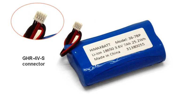
Himax 36-7BP — Samsung INR18650-35E 1S2P, 3.6V 7Ah, 25.2Wh, with GHR-4V-S connector and AWG26 output wire

The Cell Behind the Pack: Samsung INR18650-35E

Before I get into the pack-level specs, the cell selection is worth spending a moment on, because it explains a lot of the downstream performance characteristics.

The INR18650-35E is a Samsung SDI cell with a 3400mAh nominal capacity and an internal impedance of ≤35mΩ at the cell level. In the world of 18650 cells, that impedance figure is what I’d call competitive — it’s low enough that two cells in parallel maintain a combined pack impedance of ≤70mΩ, which is the spec we publish. For robot applications, internal impedance matters directly: lower impedance means less voltage sag under load peaks, which means motors get a more stable supply voltage during acceleration events.

The cell’s physical dimensions are max 18.55×65.25mm — the standard 18650 cylindrical format. The 1S2P configuration places two of these cells in parallel, which gives the pack its 6800mAh nominal (7Ah rated) capacity at 3.6V, with a minimum guaranteed capacity of 6600mAh. The two cells share current load, which also means each cell is operating at a lower C-rate than it would in a single-cell configuration — and lower C-rate cycling is one of the most reliable ways to extend calendar life in lithium-ion.

Pack Specs That Matter for Robot Designers

Energy Density: 25.2Wh in a 101-Gram Package

The 36-7BP packs 25.2Wh into approximately 101 grams — a gravimetric energy density of roughly 250Wh/kg at the pack level. For a robot where every gram of battery weight subtracts from payload capacity or extends runtime, that ratio matters. The pack dimensions are 36 × 18.2 × 67.5mm (±0.5mm), which fits the standard 18650 2-cell side-by-side footprint that most robot chassis are already engineered around.

Charge and Discharge: The Numbers and the Reality

Standard charge is 4.2V CC/CV at 1.4A for 6 hours. Max charge current is 3A. On the discharge side, standard is 1.4A with a cutoff at 2.65V, and max continuous discharge is 3A.

The 2.65V cutoff is a key spec for robot system designers. Most robot controllers set their low-voltage cutoff somewhere between 2.8V and 3.0V for conservatism, which is fine — the BMS and the controller can have complementary protection thresholds. What I want to flag is that discharging to 2.65V is the condition under which our 6800mAh nominal capacity is rated. If your system cuts off at 3.0V, your realized capacity will be somewhat lower than 6800mAh. This is a normal aspect of lithium-ion pack integration that sometimes catches product teams by surprise when their runtime doesn’t quite match the datasheet.

Samsung INR18650-35E 3400mAh 0.2C discharge curve showing capacity vs voltage profile

Cycle Life: 500 Cycles at ≥80% Capacity

After 500 standard charge-discharge cycles at 20±5°C, the pack retains at least 80% of its original capacity. For a robot used in a commercial environment — one charge cycle per operational day, five days per week — 500 cycles is approximately two years of service before the battery falls below the 80% threshold. At that point the robot still runs; it just runs for shorter periods between charges.

What I’ve observed in our aging test data is that packs using the Samsung 35E cell tend to follow a fairly predictable degradation curve — gradual, linear capacity loss rather than the cliff-edge dropout you see with lower-quality cells. That predictability matters for robot operators who want advance warning of declining battery performance rather than a sudden operational failure.


Full Pack Specification Reference

Parameter Value Notes
Cell Model Samsung INR18650-35E Premium cylindrical Li-ion
Pack Configuration 1S2P 2 cells in parallel
Cell Nominal Capacity 3400mAh 0.2C, cutoff 2.65V
Pack Nominal Capacity 6800mAh (7Ah rated) Guaranteed min: 6600mAh
Nominal Voltage 3.6V
Energy 25.2Wh
Charge Voltage 4.2V CC/CV method
Discharge Cut-off Voltage 2.65V
Standard Charge Current 1.4A 6-hour charge
Max. Charge Current 3A
Standard Discharge Current 1.4A
Max. Cont. Discharge 3A
Cycle Life 500 cycles ≥80% capacity retention
Cell Impedance ≤35mΩ 1kHz AC method
Pack Impedance ≤70mΩ Incl. protection circuit
Charge Temp. Range 0°C – 45°C
Discharge Temp. Range -20°C – 60°C
Storage Temperature -10°C – 60°C
Pack Dimensions 36 × 18.2 × 67.5mm (±0.5mm) L × W × H
Weight ~101g
Output Wire 1571 AWG26, 80±5mm
Output Connector GHR-4V-S JST GH series compatible
Standards GB/T18287-2013, UL1642, CE61960
Warranty 1 year from shipment date


Temperature Range: What -20°C to 60°C Actually Covers

First of all, the discharge temperature range is -20°C to 60°C. For robot applications this is relevant in two directions.

On the cold end: robots deployed in warehouse environments, cold storage logistics, or outdoor winter scenarios in northern climates need a battery that still delivers adequate current when the ambient is well below zero. Our electrical performance data shows temperature characteristic 2 — a -10°C soak for 3 hours followed by 1.4A discharge — yields ≥40% capacity retention. That’s a conservative threshold; in practice, you’ll typically see 50–60% retention at -10°C, with the floor at -20°C being lower. Robot designers operating in cold environments should plan their minimum-runtime requirements around the low end of this range.

On the hot end: robot motor drivers, motor housings, and dense electronics generate significant internal heat. An enclosure that runs at 35°C ambient at the battery location can spike to 50–55°C during sustained operation. The 60°C discharge ceiling provides reasonable headroom for that scenario. The temperature characteristic 1 test (40°C soak, 3 hours, 1.4A discharge) shows ≥97% capacity retention — meaning heat within the normal operating range doesn’t meaningfully degrade available capacity.

What We Actually Check Before a Pack Ships

This is the section I find most useful to be specific about, because “quality control” appears on every vendor’s website and means something different at every factory. Here’s what our manufacturing and QC process covers for the 36-7BP:

  1. To begin with, Incoming cell inspection

Every batch of Samsung 35E cells is verified against voltage, capacity, and impedance before assembly. We match cells for the 1S2P configuration — pairing cells with similar open-circuit voltage (≤10mV spread) and similar impedance (≤10mΩ spread). Poor cell matching in a parallel configuration leads to unequal current sharing, which means one cell ages faster than the other and the pack’s effective capacity degrades faster than the cycle-life spec suggests. Tight matching is not optional; it’s what makes the 500-cycle spec achievable in practice.

  1. Aging test (formation cycling)

After assembly, each pack goes through a formation cycling process — typically 2–3 charge/discharge cycles under controlled conditions before QC measurement. Formation allows the SEI layer (solid electrolyte interphase) on the cell’s anode to stabilize, which has a direct effect on the cell’s long-term capacity retention. Packs that skip formation and ship immediately off the assembly line tend to show higher first-cycle capacity loss than their rated spec.

  1. Open-circuit voltage measurement

After formation and before shipment, we verify that each pack’s open-circuit voltage is ≥4.1V within 24 hours of the last standard charge. This is the electrical performance specification from section 7.5 of the spec sheet. Packs that don’t meet this threshold don’t ship.

  1. Capacity verification

Each pack is discharge-tested at 1.4A to 2.65V after standard charge at 20±5°C and a 1-hour rest. The measured capacity must be ≥95% of rated capacity. A pack that measures 6600mAh when it should be 6800mAh doesn’t represent a defect within the guaranteed minimum — but a pack that measures below 6600mAh does, and it gets pulled.

  1. Furthermore, packs ship at 10–30% state of charge

Packs ship at 10–30% state of charge, at a voltage of 3.5–3.7V. This is the transport condition specified by lithium-ion shipping regulations. It’s also the storage condition least likely to cause calendar aging — a pack stored long-term at full charge degrades faster than one stored at partial charge. OEM customers who hold inventory should check the voltage on receipt, top up if below 3.5V, and not leave packs fully charged in storage for extended periods.

  1. AQL inspection

Outgoing quality control is conducted under AQL 0.65% normal inspection standards. This is the acceptance quality limit used in consumer electronics manufacturing — it means that in a large batch, the accepted defect rate is below 0.65%. For OEM customers building robot products with strict reliability requirements, it’s a meaningful baseline.

Himax Electronics battery factory aging test and quality control process for Samsung 18650 Li-ion robot battery packs

Robot Applications: What Draws Engineers to This Configuration

The 36-7BP comes up in robot design conversations for a fairly specific set of reasons:

  • 6V nominal fits single-cell Li-ion architecture: many compact robot controller boards are designed for a 3V–4.2V input range that runs directly from a single Li-ion cell, without a step-up converter. This eliminates a BOM component and reduces conversion losses.
  • 7Ah is the sweet spot for 1–3 hour runtime at moderate loads: a robot drawing 2–3A average current (common in mobile platforms with drive motors and sensors) gets approximately 2–3 hours of runtime from a 7Ah pack — enough for a meaningful work shift without being oversized.
  • 101-gram weight keeps payload margins comfortable: robot designers working with payload constraints — especially in collaborative or mobile applications — can factor in 101g knowing the battery provides 25.2Wh. The energy-per-gram ratio is difficult to beat at this capacity class in a standard 18650 form factor.
  • GHR-4V-S connector is widely compatible: the JST GH series connector is one of the more common choices in compact robotics and drone electronics. Many robot controller boards have a GH-compatible mating connector already specified, which simplifies mechanical integration.
  • -20°C discharge capability covers most deployment environments. Consequently, it is a reliable choice for diverse robotic applications. logistics robots, outdoor inspection robots, and warehouse automation equipment operating in cold-chain or northern-climate environments can rely on this pack to deliver current in conditions that would shut down less capable cells.

Safety Testing: What the Pack Has Passed

The 36-7BP is built to GB/T18287-2013, UL1642, and CE61960 standards. Moreover, the safety test suite validates the pack against the conditions that represent real-world fault scenarios: The safety test suite validates the pack against the conditions that represent real-world fault scenarios:

  • Overcharge: 3× max charge rate at 4.2V constant voltage for 7 hours — no explosion, no fire.
  • Over-discharge: full charge, standby 1 hour, then 1C discharge for 2.5 hours — no explosion, no fire.
  • Short circuit: external short via 50mΩ load at ambient temperature until voltage drops below 0.1V — surface temperature stays below 150°C, no explosion, no fire.
  • Heating: 5±2°C/min ramp to 130°C, held 30 minutes — no explosion, no fire.
  • Crush: 2MPa hydraulic press at 13kN — no explosion, no fire.
  • Drop: 1 meter onto concrete, two axes — no explosion, no fire, no smoke.
  • Vibration: 6mm amplitude, 10–55Hz swept at 1Hz/min, 30 minutes per XYZ axis — no leakage, no fire, no explosion.


For robot applications that export to North American or European markets, UL1642 and CE61960 certification is typically a prerequisite for import compliance. Having a certified cell from a qualified manufacturer — Samsung SDI in this case — in a pack that also carries these certifications simplifies the product compliance documentation substantially.

A Note on the 1S4P Option (3.6V 14Ah)

For robots with higher runtime requirements, the same INR18650-35E cell is available in a 1S4P configuration at 3.6V 14Ah — double the parallel cells, double the capacity, same nominal voltage. The 14Ah option makes sense for robots with higher average current draw or longer operating cycles between charges. Both configurations share the same cell, the same connector family, and the same quality process, which simplifies supply chain management for product lines that need multiple battery options.

If your application sits at the boundary — where 7Ah gives you slightly less runtime than you need but 14Ah adds more weight than you want — it’s worth discussing the actual load profile with our engineering team. There are usually design-level options that can close that gap.

Working With Himax on Robot Battery Integration

The 36-7BP is a standard configuration that ships quickly from inventory. But standard configurations are a starting point, not a ceiling. The connector type, wire length, physical enclosure or shrink-wrap finish, and labeling can all be customized for OEM integration without changing the core cell and electrical specification.

For product teams early in the design phase, the most useful thing we can do is review your load profile data — average current, peak current, duty cycle, ambient temperature range, expected daily cycle count, and runtime requirement — and tell you whether this configuration fits, needs adjustment, or whether a different pack architecture serves you better. We’d rather have that conversation at the design stage than at the warranty return stage.

The full specification sheet for the 36-7BP is available on the Himax Li-ion battery page. For robot-specific configurations, the robot battery pack section covers our range of configurations validated for mobile robot and autonomous platform applications.

Finally, if you’re ready to discuss your specific application or want to request sample packs for evaluation, the fastest path is directly through the Himax contact page. Our engineering and manufacturing teams handle technical inquiries, so you’ll get a response grounded in how the pack is actually built — not just what’s on the datasheet.

For an overview of Himax’s broader battery manufacturing capabilities and certifications, the Himax Electronics home page is a good starting point.


About the Author


Alden is a Battery Engineer in Manufacturing & Quality Control at Himax Electronics.

With hands-on experience across battery pack production lines, aging test protocols, and

outgoing quality inspection, he oversees the processes that keep defect rates low and

performance consistent across OEM production runs. He works directly with product teams

on integration requirements and production scaling.

Built-in 18A resettable fuse and advanced Battery Management System (BMS) for safe outdoor motorized equipment power

Author: Shawn – Battery Engineer – Power System Design

Standard off-the-shelf battery packs often fail under real-world conditions. This is especially true when you design power systems for outdoor motorized equipment. I am a dedicated battery solution designer at Himax Electronics. My primary objective is to engineer custom battery architectures that eliminate these pain points.

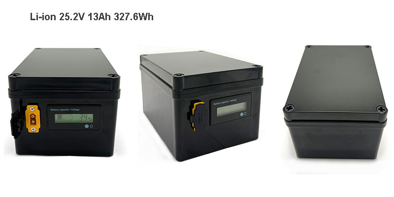
As a dedicated battery solution designer at Himax Electronics, my primary objective is to engineer custom battery architectures that eliminate these pain points. Today, I want to take you behind the scenes of a recent custom project. We specifically engineered a 25.2V 13Ah (327.6Wh) IP67 waterproof lithium-ion battery pack to reliably drive a 24V 350W motor for outdoor equipment in the UK market.

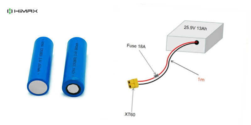
7S5P battery configuration utilizing DMEGC 18650 2600mAh 3C high-discharge cells for 24V 350W motor applications.

Cell Selection: Why We Chose DMEGC 18650 2600mAh (3C Rate)

The foundation of any high-performance battery pack is cell selection. For this specific project, our client needed a solution capable of outputting at least 15A continuous discharge current. This current powers a 24V 350W motor, especially when the trolley climbs muddy inclines under heavy load.

Instead of chasing the highest possible capacity, we prioritized discharge capability and thermal stability. We built a 7S5P architecture utilizing DMEGC 18650 2600mAh cells with a 3C continuous discharge rating.

Here is the engineering logic: A 3C rate on a 2.6Ah cell allows for roughly 7.8A of continuous discharge per cell. With 5 cells in parallel (5P), the theoretical continuous discharge capability of the pack safely exceeds 39A. This provides a massive safety margin over the required 15A continuous draw. This ensures the battery operates well below its thermal limits. It drastically reduces voltage sag during motor startup and extends the overall cycle life of the pack.

Rugged Enclosure & IP67 Waterproofing

When deploying equipment in regions with unpredictable weather like the UK, water ingress is the number one cause of battery failure. A standard PVC shrink-wrapped battery was out of the question.

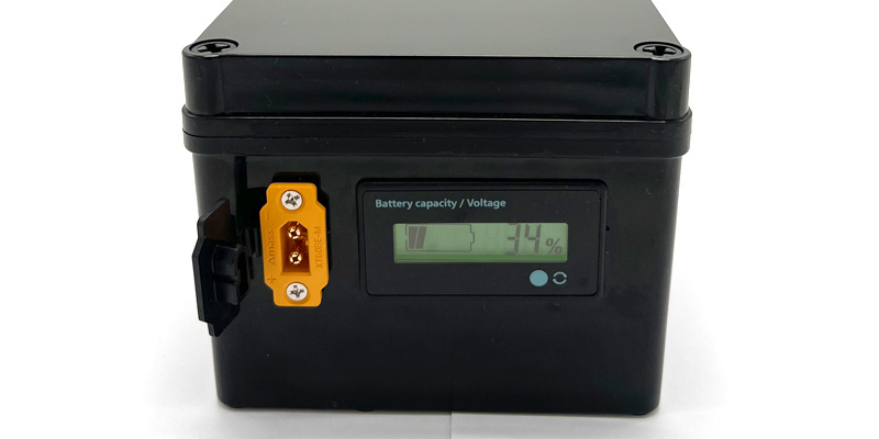
You can see this pack in the reference photo (25.2V 13Ah(1).jpg). We engineered it inside a highly durable, rigid black AG enclosure that measures precisely 175mm x 125mm x 100mm. But the real engineering happens inside the box.

To achieve a true IP67 waterproof rating, we fully seal the entire internal assembly using a specialized potting compound. This assembly includes the 7S5P cell matrix and the BMS. This potting process makes the internal electronics impervious to water immersion and heavy rain. It also acts as an excellent shock absorber. This protects the spot welds and nickel strips from the continuous mechanical vibrations of the trolley rolling over rough terrain.

IP67 waterproof 25.2V 13Ah lithium battery pack in rigid black enclosure with XT60 connector and LCD voltage display.

Smart Interfaces and Dual Safety Protection

A well-designed battery should communicate seamlessly with the end-user while protecting the equipment it powers. We integrated two specific external features to enhance usability:

1.Flush-Mounted LCD Display: Users can instantly read the exact battery capacity percentage and real-time voltage. They don’t need to power on the main equipment or use external meters.

2.Weatherproof XT60BE Connector: We utilized a panel-mounted XT60BE male connector equipped with a custom black rubber cover. This keeps the high-current connection dry and free of mud and debris. It does so even when you detach the battery for charging.


For safety, we need a standard Battery Management System (BMS). It prevents overcharge (max 29.4V), over-discharge, and short circuits. Outdoor motors can stall if a wheel gets stuck in mud, causing massive current spikes. Knowing this unpredictable nature, we integrated an additional 18A resettable fuse. If the motor stalls and attempts to draw dangerous levels of current, the fuse will trip instantly. This protects both the motor controller and the battery pack. Once the fault is cleared, the system easily resets.

Partner with a True Battery Solution Designer

At Himax Electronics, we differentiate ourselves by being more than just an assembly line. We are an expert battery solution designer. We understand that the battery cannot be an afterthought. Whether you are building heavy-duty tracking equipment, outdoor mobility tools, or sophisticated portable power stations, this principle holds.

If your current battery suppliers fail to meet your environmental, mechanical, or electrical requirements, then it is time to upgrade your power architecture. Get in touch with our engineering team via our contact page to discuss how we can design and manufacture a custom battery solution tailored exactly to your product’s demanding specifications.

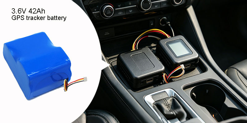
Samsung INR18650-35E 1S12P 3.6V 42Ah 151.2Wh GPS tracker battery pack with I2C communication and Molex connector for OEM devices

Author: Alden – Battery Engineer, Manufacturing & Quality Control

It is an undisputed fact in the industry: the gps tracker battery is evolving from a lifespan measured in weeks to one measured in years. However, while hardware engineers exhaust themselves trying to push standby power consumption down to a few microamps on the PCB, the battery requirements on many procurement BOMs remain a vague “18650≥3000mAh.”

This kind of ambiguous specification is a ticking time bomb for volume purchasing. Cells from different brands—or even different batches from the same brand—can have wildly different internal resistances, self-discharge rates, and aging curves. A device might perform perfectly on a lab bench, but drop it in a shipping container for six months or expose it to a harsh North American winter, and a sudden current spike during transmission can instantly drag the voltage down, causing the device to reboot.

Today, I am not going to break down a concept on a drawing board. I am going to analyze a real, mass-produced order (Project Number: HIMAX3071) designed by our IoT battery solutions team and shipped to North American clients. This is a 3.6V / 42Ah / 151.2Wh / I²C battery pack based on the Samsung INR18650-35E. Through this 1S12P architecture, I want to discuss with hardware engineers and procurement managers how to define a tracker battery that actually works, straight from a manufacturing and quality control perspective.

The Samsung 35E Cell: An Engineering Choice

There is more than one way to squeeze 3500mAh out of an 18650 form factor. So why did we strictly specify the original Samsung INR18650-35E (NMC chemistry, 3.6V nominal voltage) for this project?

Many buyers like to compare cycle life numbers on a spec sheet. But as a quality engineer monitoring the aging racks, I look at reality: Selecting a cell isn’t about picking the highest number on a spec sheet; it’s about choosing the most stable batch-to-batch performance.

The true engineering value of the Samsung 35E lies in its low internal resistance and exceptional batch consistency. The AC internal resistance of the 35E is stable at around 45mΩ, significantly lower than many cheaper competitors of the same capacity. Low IR means less internal heat loss and a smaller voltage drop when facing high-current pulses. When 10,000 cells arrive from a Tier 1 supplier, our IQC capacity and IR grading tests show the vast majority falling into an incredibly tight normal distribution curve. This consistency is the foundation for multi-cell parallel connections. If you choose an unstable cell just to save a few cents, you will pay for that mistake during testing, after-sales support, and RMAs.

From 3500mAh to 42Ah: Decoding the 1S12P Architecture

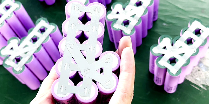
To engineer a true GPS tracker with very long battery life, a single 3500mAh cell simply isn’t enough. The HIMAX3071 design utilizes a 1S12P configuration—twelve Samsung 35E cells wired in parallel.

By putting 12 cells in parallel, we increase the total capacity to 42Ah while maintaining the system voltage at 3.6V. This directly translates to 151.2Wh of total energy. With a cell energy density of 245Wh/kg, we can pack 151.2Wh tightly into a blue PVC shrink wrap the size of a hand.

What does this mean in practice? If your tracker has an average standby consumption of 5mA, this battery can theoretically keep the device running for 8,400 hours (about 350 days). Paired with an optimized sleep strategy, the maintenance-free cycle of the device can easily be stretched to two or three years.

Diagram showing 1S12P configuration of twelve Samsung 35E 18650 cells for 42Ah 151.2Wh GPS tracker battery with very long battery life

The Necessity of I²C Communication

At a massive 42Ah capacity, relying solely on Open Circuit Voltage (OCV) to estimate remaining power is highly inaccurate, especially since NMC cells have a long, flat voltage plateau in the middle of their discharge curve.

This specific BMS requires I²C communication. This is not a “nice-to-have” feature; it is a hard requirement for modern smart tracking devices. Once the I²C interface is connected, the main MCU can directly read precise State of Charge (SoC), State of Health (SoH), and cycle counts straight from the BMS. The device does not need to calculate complex OCV estimations or look up compensation tables. When the tracker reports its battery level back to the server, the data is highly accurate.

GPS Tracker Power Profiles & Battery Matching

A GPS tracker’s power consumption profile is extreme. Most of the time, it sleeps, drawing only a few microamps. But when it wakes up, searches for satellites, and fires up its LTE-M or GSM module to transmit data, it generates current spikes of 1A to 1.5A for a few seconds.

If you are using a cheap cell or a battery pack with high internal resistance, this transient spike will cause a massive voltage drop across the battery’s IR ($V = I \times R$). Even if the battery technically has 40% capacity remaining, the terminal voltage can momentarily drop below the device’s critical operating threshold, triggering a low-voltage MCU reset. The device constantly reboots, and the battery drains rapidly.

This is exactly why we designed the following charge and discharge parameters for this 3.6V Battery Backup Supply for GPRS Tracker:

  • Max Charging Current: 2A
  • Max Continuous Discharging Current: 1A
  • Peak Discharging Current: 1.5A
  • Cut-off Voltage: 3.0V (Discharge) – 4.28V (Charge)


The 1A continuous and 1.5A peak discharge ratings perfectly cover the transient power consumption of mainstream communication modules. Simultaneously, we set the discharge cut-off at a conservative 3.0V (rather than a more extreme 2.5V or 2.75V) and cap the charge at 4.28V. This restricted voltage window sacrifices a tiny fraction of usable capacity, but significantly relieves electrochemical stress on the electrodes, greatly extending the cycle life during long-term micro-charge/discharge cycles.

I2C communication BMS board with 3.0V to 4.28V cut-off control for 3.6V battery backup supply for GPRS tracker

Physical Specs and Connectors: Engineering Decisions in the Details

No detail in a well-designed industrial battery pack is arbitrary. Let’s look at the physical construction of the HIMAX3071:

  • Packa ging: Blue PVC shrink wrap. No cell brackets, no waterproof potting.
  • Wiring & Connector: 120mm exposed wire length (excluding plug), utilizing a specified Molex 0510210400 connector.


Why eliminate the brackets and waterproof potting? Because this specific battery is designed to be housed inside the protective enclosure of an indoor or vehicular asset tracker in North America. By removing the brackets and potting, we minimize the overall weight, reduce the physical footprint, and lower the BOM cost.

The choice of the Molex 0510210400 connector is a matter of contact reliability. You cannot just slap a generic “2-pin terminal” on a pack like this. The original Molex terminals have been extensively validated for contact resistance, current carrying capacity, and anti-fretting wear in vibrating automotive environments.

Battery Label Standards

To ensure compliance and traceability, the silk-screened label on this batch accurately displays all crucial engineering parameters:

Plaintext

Li-ion 18650 35E 3.6V 42Ah 151.2Wh I²C

Model: 36-42BP

Nominal voltage: 3.6V

Minimum capacity: 40Ah

Charged voltage: 4.1 – 4.2V

Cut-off voltage: 3.0V

Charging current: 1A

Discharging current: 1A (continuous)

Peak discharging current: 1.5A

Made in China

30710001…0010

(Note: The serial numbers 30710001…0010 are used for 1-to-1 quality traceability prior to OQC shipment.)

Product label and Molex 0510210400 connector on Samsung 35E 18650 GPS tracker battery with 42Ah capacity and I2C communication

Typical Application Scenarios

Thanks to its massive 42Ah capacity and reliable discharge plateau, the 1S12P architecture is the top choice for applications demanding strict maintenance-free lifecycles:

  • Long-Haul Logistics & Freight Tracking:Cross-border shipping containers requiring uninterrupted location reporting for up to six months.
  • Fleet Management Systems: Acting as a backup power source to keep in-vehicle devices running for months after the main car battery is disconnected.
  • High-ValueAsset Trackers: Location monitoring for construction machinery and rental power generation equipment.


Himax’s Custom Design & Quality Moat

Writing parameters on a piece of paper is easy. However, designing and producing 10,000 battery packs that perform exactly like the prototype is the hard part. Do you need 1S12P or 2S6P? I²C or SMBus? Molex or JST? Himax Electronics designs custom battery solutions tailored directly to your specific BOM.

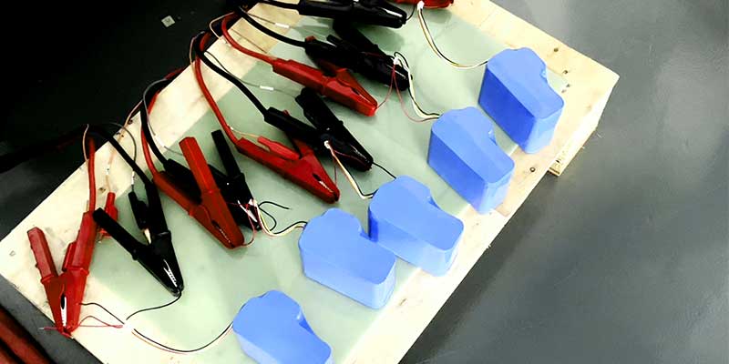
Starting from the IQC (Incoming Quality Control) phase, we perform 100% inspection and matching on original Samsung cells. Additionally, we monitor internal resistance shifts during the spot‑welding and assembly phases (IPQC). Before shipping (OQC), every single finished battery pack must complete a minimum of two full charge/discharge cycles on our aging cabinets. Finally, we strictly control the shipping SOC between 30% and 50%. This minimizes anode electrochemical stress while strictly adhering to IATA and IMDG international shipping safety thresholds.

Conclusion

The lifespan of a gps tracker battery is not determined when writing the marketing brochure. Instead, it is decided when selecting the cell, engineering the architecture, and running the aging tests. If you are tired of dealing with substandard batteries and erratic batch internal resistances, or if your devices are facing severe battery life bottlenecks, then it is time to upgrade your power design.

To dive deeper into the engineering specs of this battery solution, visit our product page: Lithium Ion Battery 3.6V 42Ah. If you need test samples, complete technical datasheets, or want to discuss a custom design for your device, initiate an inquiry directly through our Contact Page. Our engineering team will provide you with a real, reliable technical evaluation.

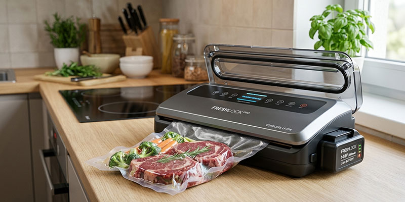
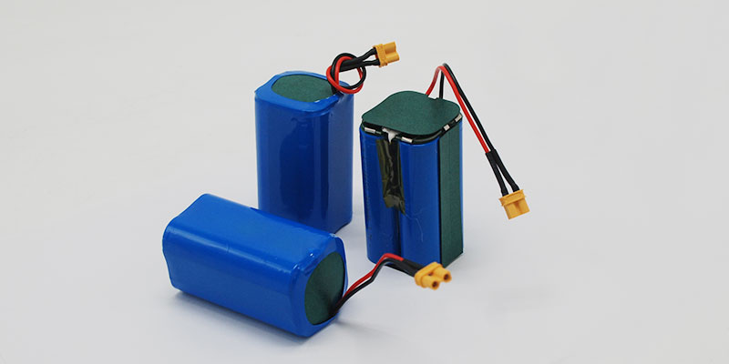
14.8V 2200mAh lithium-ion battery pack for vacuum sealer applications

Introduction

Vacuum Sealer Battery is a critical power source for cordless food packaging machines, directly affecting suction strength, sealing temperature stability, and overall packaging performance.

Modern portable vacuum sealers require a battery system that can support both vacuum pump motor startup currents and continuous heating sealing loads without voltage drop.

A 14.8V 2200mAh lithium-ion vacuum sealer battery pack is widely used in OEM cordless sealing equipment because it offers stable discharge performance, compact size, and long cycle life.

For manufacturers developing cordless vacuum sealing machines or mobile food packaging systems, selecting the right battery pack is essential for ensuring consistent sealing quality and user experience.

About the Author

Nath is a Battery Engineer specializing in lithium battery design, cell performance optimization, and OEM energy storage solutions. His work focuses on improving discharge stability and helping manufacturers develop reliable battery systems for portable electronic and industrial equipment.

Featured Answer: What is a Vacuum Sealer Battery?

A vacuum sealer battery is a rechargeable lithium-ion battery pack designed to power portable vacuum sealing machines. It provides stable voltage for both the vacuum pump motor and heating sealing system, enabling cordless operation for food packaging equipment.

Lithium-ion Battery for Cordless Food Packaging Machines

Vacuum sealer battery packs are mainly used in cordless vacuum sealing systems where stable energy output is required for suction and heat sealing processes.

Common search terms include:

  • cordless vacuum sealer battery pack
  • rechargeable vacuum food sealer battery
  • 8V lithium ion vacuum sealer battery
  • portable food sealing machine battery

These systems are widely used in households, commercial kitchens, and mobile food processing applications.

👉 Explore full food industry battery solutions:
https://www.himaxelectronics.com/food-processing-battery/

Why 14.8V Lithium-Ion Battery Is Ideal for Vacuum Sealers

14.8V=3.7V×414.8V = 3.7V \times 414.8V=3.7V×4

A 14.8V lithium-ion battery pack is typically built using a 4-series (4S) lithium cell configuration, making it suitable for vacuum sealing machines requiring stable medium-voltage power.

Key advantages include:

  • Strong startup current support for vacuum pumps
  • Stable output for heating sealing bars
  • Compact size with balanced runtime
  • Higher efficiency than 12V lead-acid systems

14.8V 2200mAh Vacuum Sealer Battery Specifications

Item Value
Battery Chemistry Lithium-Ion
Configuration 4S1P (18650 cells)
Nominal Voltage 14.8V
Capacity 2200mAh
Energy 32.56Wh
Protection Built-in BMS
Rechargeable Yes
Customization OEM/ODM supported

👉 View product details:
https://www.himaxelectronics.com/product-item/14-8v-2200mah-li-ion-battery/

Custom connector and cable design for portable vacuum sealer battery pack

Common Power Issues in Vacuum Sealers and Solutions

Weak suction performance

Occurs when battery voltage drops during vacuum pump startup.
✔ Solution: high-discharge lithium-ion battery pack with stable voltage output.

Inconsistent sealing quality

Heating elements require stable power input for uniform sealing.
✔ Solution: low internal resistance lithium cells with BMS protection.

Short runtime

Insufficient capacity leads to frequent charging interruptions.
✔ Solution: optimized 2200mAh or higher capacity battery design.

Applications of Lithium-ion Battery Packs

  • Cordless vacuum sealing machines
  • Portable food packaging equipment
  • Commercial kitchen sealing systems
  • Mobile food processing devices
  • Outdoor food preservation tools
  • Rechargeable food storage devices
  • Compact vacuum packaging systems

Rechargeable lithium-ion battery powering a cordless vacuum sealing machine

How to Choose the Right Vacuum Sealer Battery

When selecting a battery pack, OEM manufacturers should evaluate:

1. Voltage compatibility

Ensure match with vacuum pump and heating system (typically 12V–16V range).

2. Discharge performance

Must support high startup current without voltage drop.

3. Cycle life

High-quality lithium-ion batteries support 500+ cycles.

4. Mechanical design

Battery size, connector type, and wiring must match device structure.

5. Safety protection

Includes:

  • Overcharge protection
  • Over-discharge protection
  • Overcurrent protection
  • Short circuit protection

OEM Vacuum Sealer Battery Customization

We provide OEM/ODM battery solutions for vacuum sealing equipment, including:

  • Voltage and capacity customization
  • Connector and cable design
  • Battery pack dimension optimization
  • BMS protection system configuration
  • Private label branding

Common Battery Problems in Vacuum Sealers

If the battery is not properly designed, users may experience:

  • Reduced suction power due to voltage drop
  • Inconsistent sealing temperature
  • Short operating time between charges
  • Premature battery aging

A properly engineered lithium-ion battery pack solves these issues effectively.

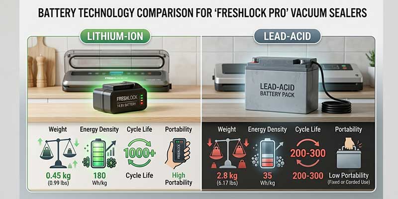
Lithium-Ion vs Lead-Acid Batteries for Vacuum Sealers

Feature Lithium-Ion Lead-Acid
Energy Density High Low
Weight Light Heavy
Cycle Life Long Short
Charging Speed Fast Slow
Maintenance Low High
Portable Use Excellent Limited

High-performance battery pack for food packaging and vacuum sealing

Frequently Asked Questions

Q1. What is the best battery for a cordless vacuum sealer?
A 14.8V lithium-ion battery pack is the most common solution.

Q2. How long does a vacuum sealer battery last?
Typically 500+ charge cycles depending on usage conditions.

Q3. Can I use a 12V battery instead of 14.8V?
Not recommended, as it may reduce suction and sealing performance.

Q4. What affects runtime?
Pump power, heating load, usage frequency, and battery capacity.

Q5. Can vacuum sealer batteries be customized?
Yes, OEM customization is fully supported.

Key Takeaways

  • 8V lithium-ion batteries provide stable power for cordless vacuum sealers
  • Battery performance directly affects suction and sealing quality
  • OEM customization improves product reliability
  • Proper battery selection reduces failure rates and maintenance costs

Conclusion

A Vacuum Sealer Battery is a core component in portable food packaging equipment, directly determining performance stability and user experience.

The 14.8V 2200mAh lithium-ion battery pack offers an optimal balance of power, size, and durability for modern cordless vacuum sealing systems.

Contact Us

Need a custom vacuum sealer battery solution?

👉 Contact us:
https://www.himaxelectronics.com/contact/

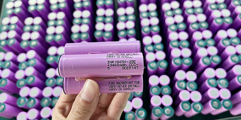
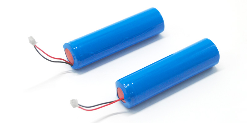
Samsung INR18650-35E 3400mAh 18650 cell for GPS locator battery - top and side view
About the Author

Shawn  |  Battery Engineer – Power System Design

With over 10 years of experience in lithium battery system design, Shawn specializes in Li-ion, LiFePO4, and LiPo battery packs. His expertise includes BMS integration, thermal management, and custom power solutions for medical and consumer devices.


Key Takeaways

  • Cell selection is a system-level decision, not a commodity choice: Engineers specify the Samsung 35E by name because its discharge curve, internal resistance, and manufacturing consistency are validated at volume. These properties directly affect warranty return rates across an 11,000-unit production run.
  • GPS locator power consumption is dominated by RF transmission bursts: A 1A continuous / 1.5A peak protection rating maps directly to LTE-M and GSM transmission current spikes. Understanding this shapes every downstream component decision.
  • PCM geometry and placement are as important as protection thresholds: A circular protection board placed at the discharge end of a 1S1P 18650 pack determines heat dissipation path, connector accessibility, and short-circuit fault tolerance.
  • The 50% state-of-charge shipping requirement has a specific engineering rationale: Shipping at 50% SoC minimizes electrochemical stress on the anode while satisfying IATA/IMDG transport safety thresholds.
  • 28AWG wire at 70mm with Molex 0510210200 is a defined interface contract: Wire gauge, length, and connector PN together specify contact resistance, current capacity, and mating force — each affects system reliability in vibration-prone tracking installations.


1. Why Cell Selection Matters More Than It Seems: The Case for Samsung 35E

When a GPS locator manufacturer specifies Samsung INR18650-35E by name rather than writing “18650 ≥3000mAh,” that specificity reflects a design decision that took engineering time to validate. Many 18650 cells nominally rated at 3000–3500mAh exist on the market, but they differ materially in internal resistance, cycle-life retention, low-temperature performance, and — critically — manufacturing consistency across production lots. For a product shipping 11,000 units to the US market in a single purchase order, lot-to-lot cell consistency is a reliability requirement that affects warranty return rates.

The Samsung INR18650-35E uses a nickel-manganese-cobalt (NMC) cathode chemistry with a nominal voltage of 3.6V and a rated capacity of 3400mAh (12.24Wh). Its internal resistance at 1kHz is specified at approximately 45mΩ — meaningfully lower than many competing cells at this capacity tier. Lower internal resistance translates directly to reduced voltage sag during the 1–1.5A transmission bursts that define GPS locator current demand. The standard charge cutoff of 4.2V and discharge cutoff of 3.0V define a conservative window that, combined with the 1A charge rate in this application, supports extended cycle life well beyond the expected service life of the GPS device.

For GPS locator OEMs evaluating cell sourcing, Samsung 35E also offers a practical supply chain advantage: it is produced by a Tier 1 manufacturer with publicly available, independently verified test data. This matters when downstream customers or regulatory auditors request battery cell documentation as part of product qualification — a requirement increasingly common in commercial fleet management and insurance-grade asset tracking applications.

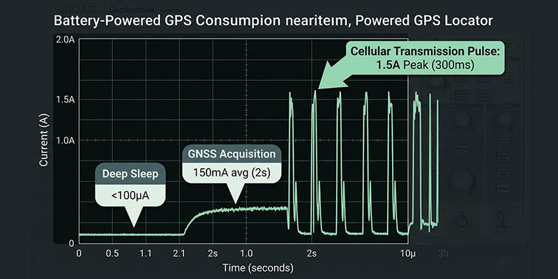
GPS locator current consumption waveform: deep sleep, GNSS acquisition, and cellular transmission pulses up to 1.5A peak

2. Decoding GPS Locator Power Consumption: What 1A/1.5A Actually Covers

A typical GPS locator combines GNSS positioning with cellular reporting (GSM 2G, LTE-M, or NB-IoT). It operates in a duty-cycled pattern. Most of the interval, it stays in deep sleep, consuming microamps. Then it wakes to acquire a fix. That fix takes 50–200mA for 1–5 seconds. Next, it transmits via cellular, typically drawing 500mA–1.5A for 200–500ms. The 1.5A peak rating is specifically sized to cover the worst-case cellular transmission burst — a device attempting registration on a weak GSM signal can transiently demand 1.5A or more. If the protection board’s peak threshold is set too low, it disconnects the battery at exactly the moment the device needs it most.

The 1A continuous discharge rating covers GNSS acquisition and processing, and provides thermal safety margin for sustained operation in enclosed installations where ambient temperature may reach 50–60℃. At these temperatures, a 1A continuous current through a 45mΩ cell produces approximately 45mW of internal heat. This heat is manageable within the thermal budget of a properly designed single-cell pack. Nevertheless, engineers must explicitly check this parameter.

Runtime estimation requires an energy-based model. Assume a 60-second GPS reporting interval. That interval includes 2 seconds of GNSS acquisition at 150mA. It also includes 300ms of cellular transmission at 1.2A average. The remaining 57.7 seconds are deep sleep at 20mA. Under these conditions, the average current is approximately 50–70mA. At 60mA average, a 3400mAh cell provides roughly 56 hours of continuous operation — consistent with the 2–3 day typical service interval quoted in commercial GPS locator product sheets.


3. PCM Design: Why a Circular Protection Board at the Discharge End Is the Right Architecture

The specification calls for a circular protection board placed at the discharge end of the 18650 cell, with cutoff voltage set at 3.0V discharge and 4.2V charge. A circular PCM sized to the 18650 cross-section (~18.5mm diameter) integrates cleanly with the blue PVC heat-shrink packaging. Why choose a circular form? It places the PCB coplanar with the cell’s negative terminal. There, protection MOSFETs and sense resistors have direct thermal contact with the cell can. This arrangement facilitates passive heat transfer toward the cooler exterior. As a result, it avoids trapping heat between the cell and the PCB.

The over-discharge cutoff at 3.0V is deliberately conservative relative to the cell’s absolute minimum (~2.5V). Operating the Samsung 35E below 3.0V under load accelerates lithium plating on the graphite anode. This causes measurable capacity fade within 100 cycles. Therefore, the 3.0V cutoff protects calendar life in GPS locators. These devices may experience extended discharge events without scheduled recharging. The over-charge cutoff at 4.2V is the standard maximum for NMC chemistry; exceeding 4.25V initiates irreversible cathode oxidation and is the primary cause of cell swelling failures.

The Molex 0510210200 (2-pin, 1.25mm pitch) connector with crimped terminal (PN: 0500798000) represents a defined interface rather than a generic JST-style connector. The Molex Pico series is rated for 1A per contact with defined insertion/withdrawal force and retention specification — relevant for GPS trackers installed and removed from vehicle OBD ports or magnetic mounting fixtures multiple times over their operational life.


4. Wire Specification: Why 28AWG at 70mm Is a System-Level Constraint

28AWG copper wire has a resistance of approximately 213mΩ/m. At a total length of 70mm (both conductors), the combined resistance contribution is about 30mΩ. This value is measurable against the cell’s 45mΩ internal resistance and contributes to the total voltage drop during peak transmission events. At 1.5A peak, this 30mΩ produces a 45mV additional voltage drop that the system designer must budget for in minimum operating voltage calculations.

The 28AWG rating also defines current-carrying capacity: at 1.5A continuous, 28AWG copper with standard PVC insulation operates well within its thermal rating for short bundled runs in free air. The specification is intentionally derated. In other words, 28AWG could carry higher currents. However, specifying it at 1A/1.5A provides safety margin. It also keeps wire temperature rise below the PVC insulation thermal limit in the enclosed installation environment of a GPS locator housing.

The 70mm length including connector provides adequate routing slack for strain relief without creating excess length that must be folded and compressed inside the housing. Folded wire is a common source of insulation abrasion failures in high-vibration vehicle installations. OEM device designers should treat the 70mm specification as a mechanical interface requirement, not a rough guide.

Circular protection circuit board (PCM) placed at the discharge end (negative terminal) of an 18650 cell for GPS tracker battery pack

5. Label Compliance and Shipping Requirements for the US Market

The label specification declares: INR18650-35E 3.6V 3400mAh 12.24Wh, with charging and discharging currents stated. These data fields are required by US DOT Hazardous Materials Regulations (49 CFR Part 173) for lithium battery transport. They also align with IEC 62620 labeling requirements for secondary lithium cells in industrial applications.

The 12.24Wh declaration is the key transport classification threshold. Under IATA Dangerous Goods Regulations and 49 CFR §173.185, lithium-ion cells with Wh ≤20Wh qualify for transport as Section II lithium batteries — the most permissive classification, requiring no dangerous goods declaration for most air freight scenarios. The Samsung 35E at 12.24Wh falls comfortably within this threshold. For an order of 11,000 units, correctly classifying the battery at ≤20Wh per cell avoids a freight compliance problem that could delay an entire production delivery.

The 50% SoC requirement for shipping balances three competing requirements: (1) the cell must have enough charge to power the device for incoming inspection; (2) the cell must not be at full charge, where any fault during transit releases maximum energy; and (3) storage at 50% SoC minimizes anode lithium plating and capacity fade during the weeks or months the battery may spend in transit and warehouse storage before integration. The factory registration code on the label (Made in China 31500001…0200) provides traceability required for Chinese lithium battery export declaration under customs HS code 8507.60.


6. Application Context: GPS Locator Power Architecture Considerations for OEM Designers

For OEM engineers integrating this battery into a GPS locator product targeting the US market, several system-level decisions flow directly from the battery specification:

Charger Design

The 1A maximum charge current and 4.2V charge voltage define the CC/CV charger specification. IEC 61960 requires that chargers follow battery manufacturer parameters and only initiate charging within a safe temperature window (typically 0–45℃ for NMC). A charger that ignores cell temperature and charges at 1A in a -10℃ environment will cause lithium plating regardless of the PCM’s voltage-based protections — temperature-aware charging is a firmware requirement, not only a hardware one.

Connector Interface

The Molex 0510210200 (2-pin) connector provides battery voltage only — no SMBus, no thermistor output, no authentication. If the end device requires battery SoC estimation (fuel gauge), this must be implemented on the device PCB using a coulomb-counting IC (e.g., Texas Instruments BQ27427) with the battery connected through a known sense resistor. Alternatively, the battery design can be upgraded to include a 3-wire or 4-wire connector with thermistor and authentication outputs — a common next-step request as GPS locator OEMs add fleet management features.

Housing Thermal Design

A blue PVC-wrapped 18650 in a sealed GPS locator housing creates a thermal resistance path that matters at sustained 1A discharge. At 60℃ ambient (parked vehicle in summer), the combination of elevated ambient and internal heat generation can push cell temperature toward 70–75℃ during sustained transmission events. NMC cells operated above 60℃ sustained exhibit accelerated SEI layer growth and capacity fade. Good GPS locator housing design includes a thermal path — such as the cell in contact with an aluminum housing wall — that limits steady-state cell temperature to below 55℃ even at maximum rated ambient.

GPS locators are a key segment of the broader Internet of Things (IoT) ecosystem. For designers working on other battery-powered IoT devices — such as asset trackers, environmental sensors, or smart logistics tags — similar engineering principles apply. Explore our IoT battery solutions page to see how we optimize cell selection, PCM architecture, and connectivity for low-power wide-area network (LPWAN) and cellular IoT applications.

28AWG wire (70mm) with Molex 0510210200 2-pin connector for GPS locator battery assembly

Product Specification Summary

Parameter Value
Cell Model Samsung INR18650-35E
Configuration 1S1P
Nominal Voltage 3.6V
Rated Capacity 3400mAh
Energy 12.24Wh
Charged Voltage 4.2V
Discharged Cutoff Voltage 3.0V
Max Charging Current 1A
Max Discharging Current 1A continuous, 1.5A peak
Wire Spec 28AWG, 70mm including connector
Connector (plug) Molex 0510210200
Connector (crimp terminal) PN 0500798000
Protection Board Circular PCM, discharge-end placement
Packaging Blue PVC heat shrink
Shipping SoC 50%
Order Quantity 11,000 units
Primary Application GPS locator (US market)
Delivery Requirement 2026-06-22


Need a Custom GPS Locator Battery Solution?

Whether you require a different capacity, a specific connector, or an integrated fuel gauge for your IoT tracking device, our engineering team can tailor the design to your exact specifications. We support OEM/ODM projects from prototype to mass production — including full documentation for US DOT, IATA, and IEC compliance.

Contact our battery engineers to discuss your GPS locator power requirements, request samples, or receive a compliance package for your next product launch.

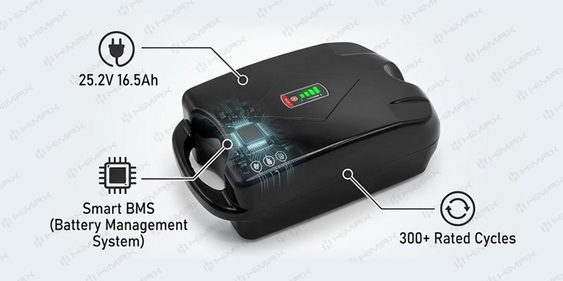
Himax 25.2V 16.5Ah 415.8Wh lithium-ion battery pack for electric golf caddy and battery powered golf push cart, model 252-165BP, white background product photo

By Caleb — Battery Engineer, BMS & Protection Systems | Himax Electronics

I’ve spent years designing BMS and protection systems for portable power applications — and few environments put a battery through its paces quite like 18 holes on a golf course. Variable terrain, temperature swings, vibration, long discharge cycles, and the occasional rough landing in a bunker. When a golf course operator or cart manufacturer comes to me asking about battery for electric golf caddy applications, the conversation goes a lot deeper than just “how many volts.”

This post is written for OEM manufacturers of golf push carts, electric golf caddy cart trolley systems, and remote-controlled models — as well as large golf course operators who spec their own fleets. I’ll walk through exactly what makes a lithium battery perform reliably round after round, and why cutting corners on BMS design is the most expensive mistake in this product category.

Why Golfers Are Ditching Lead-Acid — And What That Means for You

The shift toward battery powered golf push carts has accelerated dramatically. Talk to golfers who’ve made the switch to an electric golf caddy, and the verdict is almost universally positive: once you play 18 holes without carrying your bag, going back feels unthinkable.

The sticking point has almost always been the battery. Early adopters who bought SLA (sealed lead-acid) powered trolleys dealt with unpredictable range, excessive weight — often 6–8 kg for the battery alone — and rapid capacity fade after just one season of regular use. A well-engineered lithium-ion solution solves all three, but only if the cell selection, pack configuration, and protection electronics are designed properly from the ground up.

Here’s a quick side-by-side:

Lead-Acid Golf Cart Battery:

  • Weight: 6–9 kg for equivalent energy
  • ~200–300 usable cycles before significant degradation
  • Sensitive to partial discharge (sulfation damage)
  • No built-in protection electronics
  • Slow charge times: 8–12 hours typical
  • Performance drops sharply in cold weather

Lithium-Ion Golf Cart Battery:

  • Weight: ~2.5 kg for same or higher energy output
  • 300+ rated cycles at ≥80% capacity retention
  • No memory effect — partial charges are perfectly fine
  • Integrated BMS with multi-layer protection
  • Full charge in ~5–6 hours at standard current
  • Functional discharge range: −20°C to 60°C

For manufacturers of remote controlled electric cart systems and electric golf caddy cart trolley products, this shift represents both a market opportunity and an engineering responsibility. The battery you source defines your product’s reputation on the course — and in your warranty department.

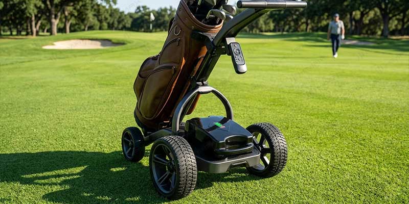
Remote controlled electric cart golf trolley on golf course fairway powered by 25.2V lithium-ion battery, 18-hole range, lightweight 2.5kg design

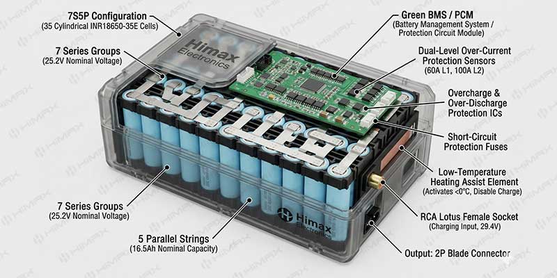
Inside Our 25.2V 16.5Ah Golf Caddy Battery Pack

At Himax Electronics, we engineered our Model 252-165BP specifically for electric golf bag caddy applications. Let me walk through the key specification parameters and explain why each one matters in real-world course conditions.

Key Specifications — Model 252-165BP:

Parameter Specification Note
Nominal Voltage 25.2V 7S configuration
Charge Voltage 29.4V CC/CV method
Nominal Capacity 16.5Ah Min. guaranteed: 16.25Ah
Energy 415.8Wh
Pack Weight ~2,534g INR18650-35E cells
Configuration 7S5P
Max Continuous Discharge 15A Standard: 3.3A
Cycle Life 300+ cycles ≥80% capacity retained
Dimensions 260×150×84mm
Operating Temp (Discharge) −20°C to 60°C
Operating Temp (Charge) 0°C to 45°C With low-temp heating assist
Internal Impedance ≤80mΩ

Why 7S5P? The Engineering Logic Behind the Configuration

The 7S5P architecture means 7 cells in series — giving us 25.2V nominal and 29.4V at full charge — with 5 parallel strings, using the INR18650-35E cell rated at 3,400mAh per cell. That combination delivers 16.5Ah at pack level with an internal impedance of ≤80mΩ.

For a battery powered golf push cart, this matters because motor load is never constant. On a steep fairway incline, an electric trolley motor can pull 8–12A momentarily. The 15A continuous rating gives comfortable headroom, while our BMS is calibrated for over-current detection at 60A (L1 trigger) with a fast-acting secondary trip at 100A (L2). You get full motor performance across undulating terrain without nuisance tripping.

“A golf battery doesn’t just need to last 18 holes — it needs to handle 300 rounds with consistent performance. That’s what 300-cycle rated capacity retention means in practice: your customer finishes their round in year two just as confidently as day one.”

BMS protection circuit module inside a 7S5P lithium battery for electric golf caddy cart trolley, showing overcharge, over-discharge, and short-circuit protection components

BMS Architecture: Why Protection Design Is Non-Negotiable for Golf Cart Batteries

This is where my work as a BMS engineer becomes central to the conversation. A lithium cell is a high-density energy storage device — and without a properly designed protection circuit module, it’s also a potential liability. Our PCM for the 252-165BP implements six distinct protection mechanisms, each calibrated specifically for mobile caddy use.

Overcharge Protection Trigger: 4.25V ±0.035V per cell | Response: cutoff within 0.5–1.5s

Critical when carts are left on charge overnight unattended in a fleet setting. A charger fault or mismatched charger can push cells beyond their safe voltage ceiling — this protection cuts the circuit before any damage occurs.

Over-Discharge Protection Trigger: 2.7V ±0.08V per cell | Resets at: 3.0V

Prevents irreversible cell damage if a cart is left powered on during off-season storage or simply forgotten in a corner of the pro shop. Auto-reset once voltage recovers — no manual reset required.

Over-Current Protection (Dual Level)

  • L1: 60A ±12A | cutoff within 0.5–1.5s
  • L2: 100A ±20A | fast cutoff 150–350ms

Handles motor stall conditions or controller faults on steep terrain. Two-stage design means everyday overload events are caught cleanly, while severe fault conditions trigger an even faster response.

Short-Circuit Protection Trigger: 200A ±40A | Response: ultra-fast cutoff 200–800µs

Particularly critical for remote controlled electric cart designs where connector engagement/disengagement is frequent. A loose or damaged connector can momentarily create a short — this protection responds in under a millisecond.

Thermal Protection

  • High-temp cutoff (charge): 65°C ±5°C | Resumes below 55°C
  • High-temp cutoff (discharge): 65°C ±5°C | Resumes below 55°C

Carts and golf bags left in car trunks during summer can exceed 60°C. This protection prevents charging under those conditions, avoiding a thermal event that most golfers wouldn’t even see coming.

Low-Temperature Heating (Charge Enable) Heating activates at: 0°C ±5°C | Turns off at: 10°C ±5°C | Max heating draw: <4A

This feature deserves special attention for any manufacturer selling into markets with cold winters. Charging lithium cells below 0°C causes irreversible lithium plating — degrading capacity and creating internal short-circuit risk over time. Our BMS activates the heating pad automatically before allowing charge current to flow. Safe, transparent, and fully automatic. No manual steps from the golfer or course staff required.

Application Fit: Golf Push Carts, Remote Caddies, and Fleet Operators

OEM Manufacturers of Electric Golf Caddy Cart Trolley Systems

If you’re producing electric golf caddy cart trolley systems at volume — whether a manual-follow model, a Bluetooth-paired caddy, or a full remote controlled electric cart — the battery is your product’s spine. The 260×150×84mm form factor of the 252-165BP fits cleanly into standard golf bag battery bays. The RCA Lotus Female Socket input and 2P blade output connector configuration make integration straightforward and compatible across common platform architectures.

Standard charging is CC/CV at 29.4V/3.3A — a full charge in approximately 6 hours, which fits naturally into an overnight retail or rental charging cycle. Max charge current support of 5A accommodates faster-charge system designs where a shorter turnaround window is required.

Large Golf Course Fleet Operations

For a golf course running 30–50 battery powered golf push carts, battery management at fleet scale introduces additional requirements beyond single-unit performance. Key factors here:

  • Cycle stability: ≥80% capacity retention over 300 rated cycles means no significant degradation through two full seasons of daily use
  • Storage retention: ≥80% charge retention after 28 days at room temperature — batteries can sit between busy weekends without significant self-discharge
  • Cold-weather performance: ≥60% rated capacity at −10°C (after 3-hour soak) covers early morning tee times in northern climates
  • Heat performance: ≥95% rated capacity at 40°C, covering summer afternoon rounds without thermal derating or unexpected shutdowns

Lead-acid vs lithium-ion golf push cart battery comparison chart showing weight, cycle life, and BMS protection advantages for golf course fleet operators

What to Ask When Sourcing a Battery for Electric Golf Caddy Applications

I’ve seen manufacturers get burned by sourcing decisions that looked good on a datasheet but failed in the field. Before you commit to a production run — with us or anyone else — here are the five questions worth asking.

1. What cell is used, and is the spec traceable?

Our 252-165BP uses the INR18650-35E with 3,400mAh nominal capacity, ≤35mΩ internal impedance, and maximum dimensions of 18.55×65.25mm. Generic “Grade A cell” claims without a specific model number are a yellow flag. You should be able to look up the cell datasheet independently.

2. Are all BMS protection thresholds documented?

Every detection threshold in our PCM — overcharge voltage, over-current detect current, short-circuit detect timing — is tested to spec and listed explicitly in our product documentation. If a supplier can’t provide this table, you don’t actually know what protection you’re buying.

3. What safety certifications apply?

Our specification is compiled with reference to GB/T18287-2013, UL1642, and IEC 61960. These standards cover mechanical abuse testing and electrical safety performance, which are relevant for any consumer or commercial market you’re selling into.

4. What do the mechanical test results look like?

The 252-165BP passes crush testing at 17.2MPa applied force, 1-meter drop testing across two axes (twice each), and vibration testing at 10–55Hz across all three axes for 30 minutes per axis. Results across all three: no fire, no explosion, no smoke. Ask for the test report before you sign a purchase order.

 5. How is storage and shelf life handled for fleet-scale orders?

Our batteries ship at a partial state of charge for transport safety, rated for storage at −10°C to 45°C, with a recommended evaluation window of 1 month from delivery. For large orders, ask about recommended check-in charging intervals for off-season storage — a fleet left untouched over winter needs a clear maintenance protocol.

Ready to Talk Spec? Let’s Build the Right Battery for Your Cart.

Whether you’re designing a new electric golf caddy product line or upgrading fleet batteries for a large golf course operation, our engineering team is ready to discuss your exact requirements — including custom pack configurations, connector specs, labeling, and volume pricing.

Contact Himax Electronics:

📩 sales@himaxelectronics.com

🌐 www.himaxelectronics.com

📞 +86 755-25629920

Shenzhen Himax Electronics Co., Ltd. — Building B, Nantong Avenue No.5, Tongle Community, Baolong Street, Longgang, Shenzhen, China

About the Author: Caleb is a Battery Engineer at Himax Electronics specializing in BMS and Protection Systems. He develops PCM/BMS solutions with overcharge, over-discharge, thermal, and short-circuit protection to enhance safety and operational stability across mobility and outdoor power applications.

11.1V 6Ah lithium ion battery pack for electric air compressor – Himax 18650 3S3P

By Shawn | Battery Engineer – Power System Design

Introduction: The Power Source Your Electric Air Compressor Deserves

Electric air compressor motors demand more from a battery than almost any other portable application. From the moment the motor spins up, it pulls high current for an extended period — and it does this repeatedly, often in harsh outdoor or industrial environments. For OEM manufacturers and bulk procurement teams sourcing a power solution that is reliable, certifiable, and easy to integrate, the choice of battery pack is a critical engineering decision, not an afterthought.

This article presents a detailed technical and commercial review of the Himax 11.1V 6Ah Lithium-Ion Battery Pack (Model: HLI-GB03-1364) — a 3S3P 18650 lithium-ion pack purpose-built for demanding motor-driven applications, including electric air compressors, electric pumps, and portable power tools.

If you are evaluating a lithium ion battery pack for your next production run, this guide gives you everything you need to make an informed decision.

Product Overview: What Is the Himax 11.1V 6000mAh Li-Ion Battery?

The Himax 11.1V 6Ah pack is a 18650 3S3P lithium ion battery pack — meaning The pack uses nine individual 18650 cells arranged in a 3-series, 3-parallel configuration. This architecture delivers a nominal voltage of 11.1V and a usable capacity of 6,000mAh (6Ah), storing 66.6Wh of energy in a compact, rugged enclosure.

Shenzhen Himax Electronics Co., Ltd. designed and manufactures it., a professional lithium battery pack manufacturer based in Shenzhen, China, with global export experience and compliance to international safety and quality standards including GB/T18287-2013, UL1642, and CE61960.

This is not a generic cell assembly. It is a finished, tested, production-ready battery pack complete with:

  • Integrated PCM (Protection Circuit Module) for cell-level safety
  • Industrial-grade XT60H-F output connector
  • Heavy-gauge AWG14 output leads (100mm)
  • Compact form factor: 58 × 63 × 68mm (±3mm)

18650 3S battery pack dimensions 58x63x68mm with XT60 connector – Himax electronics

Full Specifications: 11.1V 6000mAh Li-Ion Battery Pack at a Glance

Understanding the complete electrical profile of a battery pack is essential before committing to a design. Below are the full specifications for the Himax HLI-GB03-1364.

Cell-Level Specifications

Parameter Value
Cell Type Lithium-ion 18650
Cell Model Li-ion 18650-2000
Cell Nominal Voltage 3.7V
Cell Nominal Capacity 2000mAh
Cell Minimum Capacity 1950mAh
Cell Internal Impedance ≤25mΩ
Cell Dimensions Max. 18.4 × 65.5mm
Cell Weight Approx. 43g

Battery Pack Specifications

Parameter Value
Pack Configuration 3S3P (9 cells total)
Nominal Voltage 11.1V
Nominal Capacity 6Ah (6000mAh)
Minimum Capacity 5.7Ah
Energy 66.6Wh
Charge Voltage 12.6V
Discharge Cut-Off Voltage 8.25V
Standard Charge Current 1.2A
Maximum Charge Current 3A
Standard Discharge Current 1.2A
Max. Continuous Discharge Current 12A
Charge Method CC/CV
Cycle Life ≥300 cycles @ 80% SOC
Internal Impedance ≤150mΩ
Output Connector XT60H-F
Output Wire AWG14, 100 ± 5mm
Dimensions Approx. 58 × 63 × 68mm (±3mm)
Weight Approx. 400g
Charge Temperature Range 0°C ~ 45°C
Discharge Temperature Range -20°C ~ 60°C
Storage Temperature -10°C ~ 45°C

PCM protection circuit diagram for 11.1V 6000mAh li-ion battery pack – overcharge over-discharge short circuit protection

Why This 18650 3S Battery Pack Is Engineered for Electric Air Compressors

The design of a lithium ion battery pack for an electric air compressor involves trade-offs that general-purpose battery packs simply cannot satisfy. Here is why the Himax 11.1V 6Ah pack is a strong fit for this application category.

1. High Continuous Discharge for Motor Startup

Air compressor electric motors draw significant current during startup and sustained operation. This pack supports a maximum continuous discharge current of 12A — six times its standard 1C discharge rate. The PCM is rated to handle up to 12A charge and discharge continuously, with over-current protection triggering only above 30–50A, giving the motor controller the headroom it needs without nuisance trips.

For a 11.1V system, 12A continuous translates to 133W of sustained power output — sufficient to drive compact to mid-range electric air pump motors in cordless designs.

2. Wide Operating Temperature Range

Outdoor and industrial deployments of electric air compressorequipment often encounter temperature extremes. Rigorous tests show this pack discharges across a range of -20°C to +60°C, ensuring reliable performance in cold-morning job sites and hot-environment industrial settings alike. Charge temperature is managed conservatively at 0°C to 45°C, protecting the cells from lithium plating during low-temperature charging.

Himax’s own electrical performance data confirms:

  • At +55°C: ≥90% of rated capacity retained
  • At -10°C: ≥60% of rated capacity retained

3. XT60H-F Connector — The Industry Standard for High-Current Portable Systems

The XT60H-F output connector is the de-facto standard in high-current portable power applications including RC systems, cordless power tools, and electric pumps. It is rated for sustained high-amperage connections and is mechanically robust under repeated connect/disconnect cycles. For OEM manufacturers, this eliminates the need for custom connector integration and simplifies final assembly.

4. CC/CV Charging Compatible with Standard BMS Chargers

The pack uses Constant Current / Constant Voltage (CC/CV) charging up to 12.6V, accepting up to 3A charge current. This is compatible with a wide range of off-the-shelf and OEM-integrated chargers, reducing system BOM cost for manufacturers integrating this pack into a finished air compressor electric motor product.

5. 3S3P Architecture for Voltage-Current Balance

The 18650 3S3P battery pack configuration (3 cells in series × 3 cells in parallel) is a well-proven architecture for 11.1V portable systems. The series strings provide the 11.1V nominal voltage required by most brushless DC and brushed DC air compressor motors in this power class, while the parallel configuration triples the current capacity and overall capacity compared to a simple 3S1P arrangement.

PCM Protection System: Safety Built Into Every Pack

Every Himax 11.1V 6000mAh li-ion battery ships with an integrated PCM that provides multi-layer protection against the most common failure modes in field-deployed battery systems.

Protection Function Trigger Threshold Response
Overcharge Detection 4.25V ± 0.025V per cell Charging cut-off within 0.5–1.5 sec
Overcharge Reset 4.15V ± 0.05V per cell Auto-resume
Over-Discharge Detection 2.7V ± 0.08V per cell Discharge cut-off within 50–150ms
Over-Discharge Reset 3.0V ± 0.1V per cell Auto-resume on charge
Over-Current Detection 30–50A Immediate cut-off
Short-Circuit Protection External short detected Immediate cut-off; reset on load removal
PCM Internal Resistance ≤35mΩ Minimizes power loss

This protection architecture means that even under misuse conditions — a shorted output cable during assembly, an over-discharged cell from extended storage, or a faulty charger — the pack will protect itself and the host equipment from damage.

Safety Test Results: Mechanical and Cell-Level Validation

For OEM buyers, regulatory compliance and real-world safety validation are non-negotiable. The Himax HLI-GB03-1364 has passed the following test protocols:

Mechanical Performance

Crush Test: Applied 13kN of force via hydraulic ram — No fire, No explosion.

Drop Test: 1-meter free-fall onto concrete, two axes — No explosion, No fire, No smoke.

Vibration Test: 10–55Hz harmonic sweep, 1.6mm amplitude, 30 minutes per axis (X/Y/Z) — No leakage, No fire, No explosion.

Cell-Level Safety

Overcharge: 3C charge rate sustained for 7 hours — No explosion, No fire.

Over-Discharge: 1C discharge for 2.5 hours — No explosion, No fire.

Short Circuit: External short at ≤50mΩ load — Surface temperature below 150°C. No explosion, No fire.

Thermal Abuse: Oven test to 130°C at 5°C/min, held 30 minutes — No explosion, No fire.

These results reflect compliance with GB/T18287-2013, UL1642, and CE61960 standards — essential documentation for product safety certification in North American, European, and Asian markets.

Electric air compressor powered by 11.1V lithium ion battery pack – portable cordless air pump motor application

Bulk Procurement: What OEM Buyers and Distributors Need to Know

For procurement teams managing volume orders of lithium ion battery packs for air compressor electric motor assemblies, supply chain reliability is as important as technical performance. Here is what Himax provides at the production level.

Pre-Shipment Quality Inspection

Each unit undergoes a three-point pre-shipment check: open-circuit voltage, internal resistance measurement, and PCM function verification. Himax applies an AQL 0.65 acceptance quality limit — one of the most stringent levels used in consumer and industrial electronics manufacturing.

Shipping State

Packs are shipped at 30–70% state of charge (shipment voltage: 11.1V – 11.85V), which is both the safest transport state for lithium-ion cells and compliant with IATA/ICAO regulations for air freight of lithium batteries.

Warranty

Himax provides a 12-month warranty from the date of shipment, covering defects attributable to the manufacturing process. This warranty is clearly scoped and backed in writing.

Customization for OEM Integration

Standard production specifications can be adapted for OEM requirements including:

  • Custom dimensions within structural limits
  • Alternative output connectors (replacing XT60H-F)
  • Different wire gauge or lead length
  • Custom labeling and packaging for private-label products
  • Voltage or capacity variants (e.g., 14.8V 4S or higher capacity 3S packs)

Contact Himax Electronics directly to discuss your production volume and technical requirements.

Frequently Asked Questions

Q: What voltage is a 3S lithium ion battery pack?

A: A 3S lithium-ion battery pack has a nominal voltage of 11.1V (3 × 3.7V). Its fully charged voltage is 12.6V and its discharge cut-off voltage is typically 8.25V (2.75V per cell).

Q: Can this 11.1V 6000mAh battery be used in an electric air compressor?

A: Yes. With a 12A maximum continuous discharge current and an XT60H-F output connector, this pack is well-suited for compact to mid-range electric air compressor motors operating in the 10–12V DC range.

Q: What is the maximum discharge current of this 18650 3S battery pack?

A: The maximum continuous discharge current is 12A. The PCM’s over-current protection triggers at 30–50A, providing a safe operating margin for motor surge currents at startup.

Q: How many charge cycles does this battery support?

A: The pack achieves ≥300 cycles. while retaining ≥80% of its original capacity — measured at standard charge and discharge conditions (1.2A, 20±5°C).

Q: Is this battery pack approved for international air freight?

A: The pack complies with GB/T18287-2013, UL1642, and CE61960. It ships at 30–70% SOC in accordance with IATA lithium battery transport guidelines. Buyers should confirm specific import documentation requirements for their destination country.

Q: What charger does this battery require?

A: Use a CC/CV lithium-ion charger rated for 12.6V with a charge current of 1.2A (standard) to 3A (maximum). Do not use lead-acid or NiMH chargers, and do not exceed 12.6V charge voltage.

Conclusion: A Production-Ready Power Solution for Air Compressor OEMs

The Himax 11.1V 6000mAh li-ion battery pack delivers the combination of voltage, current capacity, protection depth, and manufacturing quality that electric air compressor OEMs and bulk buyers require. Its 18650 3S3P architecture, 12A continuous discharge capability, multi-layer PCM protection, industrial XT60H-F connector, and compliance with international safety standards make it a dependable, integrator-ready power source for portable and semi-stationary electric air compressor motor applications.

Whether you are sourcing for your own production line, evaluating a battery replacement for an existing product, or developing a new cordless air compressor design, the Himax HLI-GB03-1364 is engineered to meet the demands of the application — and the expectations of the market.

Ready to discuss volume pricing, samples, or custom specifications? Visit himaxelectronics.com or contact the Himax sales team directly to request a quotation.

By Shawn | Battery Engineer – Power System Design

© Himax Electronics. All specifications subject to change without notice. Contact Himax Electronics for the latest certified documentation before finalizing any design integration.

Security patrol robot on outdoor patrol – long endurance battery application

How Himax Electronics Battery Engineer Shawn evaluates long-endurance Li-ion packs for autonomous security robots – with real test data and BMS specifications

1. Introduction: Why Runtime Defines Autonomous Security Robots

When Daxbot deploys its security robots for 8 to 10 hours of continuous patrol at 3.7 mph, every watt-hour in the battery pack directly determines mission success. A robot that stops halfway through a patrol isn’t just an inconvenience – it creates a security gap.

I’m Shawn, a battery engineer at Himax Electronics. Over the past decade, I’ve designed Li-ion, LiFePO₄, and LiPo systems for medical devices, industrial equipment, and increasingly – autonomous robots.

In this post, I’ll walk you through a real engineering case study: our 36V 15.6Ah

  •  long-endurance, medium-speed patrol scenarios
  • Why capacity alone is misleading

Liion battery pack (spec sheet ref. 1488 Spe-Li-ion-36V-15.6Ah). You’ll see:

  • How we test for for security robots
  • What BMS parameters actually mean in the field
  • How to move from a generic battery to a custom, productionready solution

If you manufacture security patrol robots, inspection robots, or any autonomous mobile robot (AMR) that prioritizes runtime over peak power, this guide is for you.

2.36V 15.6Ah Li-ion battery pack for security robots – 10S6P 18650 cells

2. What Security Patrol Robots Really Need from a Battery

Most battery discussions start and end with voltage and amp-hours. But for a security robot, the operating profile is very specific.

2.1 The RealWorld Patrol Cycle (from Daxbot)

According to Daxbot’s published data, a typical autonomous security robot:

  • Patrols randomized routesfor 8–10 hours
  • Moves at a steady medium speed(~3.7 mph)
  • Runs sensors (cameras, LiDAR, thermal) continuously
  • Sends alerts and video streams back to a command center
  • Only rarely needs a short burst of higher power (e.g., moving to an incident)

This is not a drone racer or a warehouse AGV that needs extreme acceleration. It’s a long-endurance, low-C-rate application.

2.2 Engineering Priorities for This Use Case

When I review battery requirements with robot manufacturers, I rank these three metrics above all others:

Priority Metric Why It Matters for Security Robots
1 Energy density (Wh/kg) Longer patrol time without adding excessive weight
2 Discharge voltage stability Stable sensor readings and control signals throughout the shift
3 Cycle life @ 80% SOC Lower total cost of ownership – fewer replacements over the robot’s life

👉 Peak discharge current is often the wrong focus. A 50A burst rating means nothing if the battery can’t deliver 3A steadily for 9 hours.

3. Engineering Deep Dive: 36V 15.6Ah LiIon Pack for Security Robots

Let’s open the spec sheet. Below are the key parameters from our 36V 15.6Ah pack (Model 36-156BP). Every number comes from actual GB/T18287-2013, UL1642, and CE61960 testing.

3.1 Core Specifications

Parameter Value
Nominal Voltage 36V
Nominal Capacity 15.6Ah
Energy 561.6Wh
Cell Type 18650 – 2600mAh
Configuration 10S6P
Standard Charge / Discharge Current 3.12A
Max. Continuous Discharge Current 8A
Cycle Life ≥300 cycles @ 80% SOC
Charge Temperature 0°C to 45°C
Discharge Temperature -20°C to 60°C
Dimensions (max) 198 × 130 × 70 mm
Weight ~3.2 kg

3.2 What These Numbers Mean for a Security Patrol Robot

561.6Wh energy
At a typical robot power draw of 60–70W (including sensors, drive motors, and telemetry), this pack provides 8+ hours of active patrol. In low-power standby or between patrol cycles, runtime extends further.

8A max continuous discharge
Enough to support all onboard systems simultaneously – but not over-spec’ed for unrealistic peak loads. This keeps the BMS and cells operating in a safe, efficient zone.

300 cycles @ 80% capacity
For a robot that runs one full patrol per day, 300 cycles equals roughly 10 months of daily use before capacity drops to 80%. Many customers choose to replace packs at this point, but the robot still runs – just with shorter patrols. For comparison, a generic pack might drop below 80% after 150–200 cycles.

Temperature performance (from spec sheet §7.5)

  • At 55°C: ≥90% capacity retention
  • At -10°C: ≥60% capacity retention


Why I mention this: If your robot patrols outdoor parking lots or construction sites in winter, you must account for cold temperature derating. This is a chemical limitation of Li-ion, not a defect. For extreme cold, we often recommend a heated battery box or a different cell chemistry (LiFePO₄).

3.BMS protection parameters for security robot battery – overcharge, over-discharge, over-current thresholds

4. BMS and Safety: The PCM Parameters That Matter

A battery pack without a robust protection circuit is a liability, especially for unattended security robots. Our pack uses a PCM (Protection Circuit Module) with the following thresholds (from spec sheet §5):

Protection Threshold Delay Reset
Over-charge 4.25V ± 0.05V 0.5-1 sec 4.15V ± 0.05V
Over-discharge 2.70V ± 0.05V 0.5-1 sec 3.0V ± 0.1V
Over-current 33-55A 0.5-1 sec Release load
Short circuit External short Immediate Release load

4.1 Engineering Notes on These Settings

  • Overcharge at 4.25V: We set this slightly below the cell’s absolute maximum (4.2V typical) to provide a safety margin while still allowing full charge.
  • Overdischarge at 2.70V: This is conservative. Many Li-ion cells can go to 2.5V, but cutting off at 2.7V extends cycle life – exactly what long-endurance robots need.
  • Overcurrent 3355A: This range is well above the 8A max continuous discharge, so normal operation never trips it. But it will catch a stalled motor or a severe internal fault.


For robot manufacturers, this means you can deploy the pack in unattended charging stations or hot-swap scenarios with confidence that the BMS will handle abnormal conditions automatically.

5. Common Mistakes When Sourcing Security Robot Batteries

I review battery specs for robotics OEMs every week. Here are the three most frequent errors I see – and why they hurt your product.

❌ Mistake 1: Buying on Price Alone

A cheap pack might save $30 upfront. But if it fails after 150 cycles, you’ll face:

  • Higher warranty returns
  • Customer complaints about reduced patrol time
  • Field replacement logistics


The real cost is rarely the battery itself – it’s the downtime and lost trust.

❌ Mistake 2: Focusing Only on Capacity (Ah)

Two packs can both be 15.6Ah, but one might have high internal resistance that causes voltage sag under a modest 5A load. The result: your robot’s motors starve for current halfway through a patrol, even though the “fuel gauge” still shows 40% remaining.

We measure internal resistance on every pack before shipping (spec sheet §7.2.3). Our target is ≤90mΩ for the assembled pack.

❌ Mistake 3: Using OfftheShelf Batteries Without Optimization

A standard “36V e-bike battery” might physically fit, but its BMS logic, connector, and discharge curve are tuned for a different load profile. This leads to:

  • Premature BMS trip during normal operation
  • Inefficient charging (wrong CC/CV profile)
  • Poor thermal performance in your robot’s enclosure


My advice: Start with a reference design like our 36V 15.6Ah pack, then customize. It’s cheaper and faster than starting from zero.

6. From Specification to Production: Our Engineering Support Process

When a robot manufacturer works with Himax, this is what the engineering workflow looks like.

Phase 1 – Requirements Analysis

You share:

  • Robot power profile (typical current, peak current, duration)
  • Desired patrol time (e.g., 10 hours)
  • Operating environment (temperature, vibration, humidity)
  • Mechanical constraints (size, weight, connector type)


Phase 2 – Prototype & BMS Tuning

We select cell configuration (e.g., 10S6P) and adjust BMS parameters (over-current, voltage thresholds) to match your robot’s real behavior. You receive 5–10 samples for in-house testing.

Phase 3 – Validation

We run the tests you see in this spec sheet: cycle life, temperature performance, crush, drop, vibration, and over-charge/over-discharge safety (see spec sheet §7–§9). You get a full test report.

Phase 4 – Mass Production

Each batch is inspected per AQL 0.65 (spec sheet §10.5). Shipment voltage is set to 37-39.5V (≈30-40% SOC) for safe transport, as required by UN38.3.

“The customer is requested to contact HIMAX in advance, if other applications or operating conditions than those described in this document.” – That’s not legal boilerplate. It’s an invitation to engineer together.

7. RealWorld Validation: Daxbot and the Security Patrol Market

Daxbot’s deployment in parking lots, construction sites, and retail plazas confirms what we see in our test data: long-endurance Li-ion packs enable new use cases.

From their customer feedback: “They’re a deterrent for mischief. People see them, they’re less likely to do certain things.”
But a robot that runs out of battery at 2 AM stops being a deterrent.

Our 36V 15.6Ah pack is designed for exactly that: reliable energy from the start of patrol to the end, shift after shift.

8. Conclusion: Choose a Battery Partner, Not Just a Battery

For security patrol robots, inspection robots, and autonomous security platforms, the battery is not a commodity. It’s a systemlevel component that affects:

  • Patrol time (directly tied to value delivered)
  • Field reliability (warranty costs and brand reputation)
  • Total cost of ownership (cycle life and maintenance)


At Himax Electronics, we provide more than cells and a BMS. We provide:

  • Engineering support from prototype to production
  • Consistent batch quality (tested per GB/T18287-2013)
  • Long-term supply reliability for OEM customers

Cycle life and temperature performance testing of 36V Li-ion battery pack – GB/T18287-2013 standard

9. CTA – Start Your Custom Battery Project

If you are sourcing batteries for:

  • Security patrol robots
  • Inspection robots
  • Autonomous mobile robots (AMRs)
  • Any robot that prioritizesruntime over peak power


Share your robot’s power profile and operating environment with me.

I’ll personally review your specs and recommend the closest existing design – or work with you on a custom solution. You can reference our 36V 15.6Ah Li-ion pack (spec sheet 1488 Spe-Li-ion-36V-15.6Ah) as a baseline.

📩 Contact Himax Electronics
Attn: Shawn, Battery Engineer
Include: robot model, target patrol time, operating temperature range, estimated annual volume.

About the Author

Shawn – Battery Engineer, Power System Design
10+ years in lithium battery system design (Li-ion, LiFePO₄, LiPo). Specializes in BMS integration, thermal management, and custom power solutions for industrial robotics and medical devices.

Himax Electronics
ISO-compliant battery manufacturer with in-house engineering support.
📍 Shenzhen, China | 🌐 www.himaxelectronics.com

*Data sources: Internal test reports based on GB/T18287-2013, UL1642, CE61960 standards. Security robot patrol data referenced from Daxbot (daxbot.com/security-robots).*

Tol battery

As we push further into 2026, the Internet of Things is no longer about simple, low-power sensors sending tiny data packets. Today’s IoT landscape is defined by sophisticated edge computing, high-bandwidth cellular transmissions, and complex sensor arrays. These devices demand more from their power sources than ever before. For over 12 years, I’ve specialized in designing custom Li-ion packs for these exact challenges. My name is Alden, and I’m a Battery Systems Engineer here at Himax Electronics. In my experience, one of the most common failure points I see in otherwise brilliant IoT projects is an under-specified power source. That’s why I’m excited to share my insights on a solution that is quickly becoming the new standard for reliability and performance: the high-discharge 3.7V 6000mAh Li-ion battery pack.

a compact 1S2P configuration with 18650 cells

Understanding Power Demands in Modern IoT Devices

The days of a simple, steady power draw are over for most serious IoT applications. A modern industrial IoT sensor or remote gateway has a highly dynamic power profile. It might idle at a few microamps for hours, then suddenly demand several amps for a few hundred milliseconds. This “bursty” behavior is the new normal.

A common mistake I see engineers make is designing for the average current draw, not the peak. This leads to catastrophic field failures. When a device needs to power up a 4G/5G modem, actuate a motor, or fire up multiple sensors simultaneously, the battery’s voltage can plummet if it can’t handle the sudden load. This “voltage sag” or “brownout” can cause the device’s microcontroller to reset, corrupting data and leading to a spiral of failed connection attempts that drains the battery completely. A robust IoT battery must be able to handle these peaks without faltering.

Why 3.7V 6000mAh with 18A Discharge Stands Out for IoT

At Himax, we’ve focused on creating a power solution that directly addresses these modern challenges. Our 3.7V IoT battery pack is built to provide both endurance and power, serving as a reliable power solution for edge IoT devices. Let’s break down what makes this configuration so effective.

Here’s what makes our Himax IoT battery, a 1S2P 18650 battery for IoT, a game-changer:  

  •  High Capacity (6000mAh): Built with two premium 3000mAh 18650 cells in a 1S2P configuration, this pack offers a substantial 6Ah of energy. This high capacity is essential for achieving a long operational life in remote or solar-powered IoT deployments, minimizing the need for costly and frequent replacements. It’s the foundation of a low total cost of ownership.
  • Massive Discharge Capability (18A): This is the crucial spec. A continuous discharge rating of 18A means the battery can effortlessly handle the intense power spikes from LoRaWAN, NB-IoT, or 5G transmissions. This prevents voltage sag, ensuring your device remains stable and operational during its most critical tasks. This is a true high discharge IoT battery.
  • Ultra-Compact Form Factor: Space is always at a premium inside an IoT enclosure. With dimensions of just 38 × 25 × 70 mm, this rectangular pack is incredibly dense. It allows you to design smaller, more discreet devices without sacrificing power, a key advantage for asset trackers and compact industrial sensors.
  • Industrial-Grade Reliability: We designed this 3.7V 6000mAh 18650 pack for the real world. Paired with a properly designed Battery Management System (BMS), it offers excellent thermal stability and a long cycle life, operating reliably in harsh environments typically ranging from -20°C to 60°C.


Real-World IoT Applications Where This Pack Excels

The combination of high capacity and high discharge in this Li-ion battery for IoT devices makes it incredibly versatile. Here are a few applications where I’ve seen this type of pack deliver exceptional results:

Smart Agriculture Sensors: A soil moisture and nutrient sensor array might take readings every hour, but once a day it needs to transmit a large data log over a cellular network. That transmission burst requires a high discharge IoT battery to ensure the data gets through, while the 6000mAh capacity allows it to last for an entire growing season. This is a perfect use case for a high capacity battery for remote monitoring.

Industrial Asset Tracking & Cold Chain: A tracker on a shipping container needs to survive for months while providing periodic GPS/cellular location updates. When moving through areas with poor signal, the modem boosts its power, drawing significant current. An 18A continuous discharge battery ensures the tracker doesn’t fail when it’s needed most.

Remote Environmental Monitoring: Consider a solar-powered gateway in a remote forest monitoring for fire risk. The system charges during the day and runs on its 3.7V 6Ah battery for IoT at night, powering sensors and a satellite modem. The battery’s ability to handle high peak currents is critical for reliable data transmission, no matter the conditions.

designed for high-discharge industrial IoT applications.

Engineering Tips: Integrating High-Discharge Packs Without Over-Engineering

From my experience as Alden, a Battery Systems Engineer, I believe a great battery is only half the solution. Proper integration is key. Here’s what to look for when incorporating a high-performance 3.7V IoT battery pack into your design:

  • Don’t Skimp on the BMS: The Battery Management System is the brain of your power system. For a high-discharge pack, ensure your BMS provides accurate cell balancing, over-current protection that aligns with the 18A peak, and under-voltage/over-voltage cutoffs to maximize cycle life.
  • Consider Your Connectors: A common point of failure is a connector that isn’t rated for the peak current. An 18A pulse will generate heat and voltage drop across a flimsy connector. Use connectors with an appropriate current rating to ensure all that power makes it to your device.
  • Thermal Management is Your Friend: While our 18650 cells are incredibly stable, all batteries generate heat under load. In a tight, sealed enclosure, ensure there’s a thermal pathway for this heat to dissipate. Even a small piece of thermally conductive material can make a huge difference in long-term reliability.
  • Himax 3.7V 6000mAh Li-ion IoT battery pack

Looking Ahead — The Role of Reliable Batteries in Scaling IoT Deployments

Looking ahead, as Alden at Himax Electronics, I see the reliability of each node becoming exponentially more important. The difference between a pilot project and a global deployment of a million devices often comes down to Total Cost of Ownership (TCO). A robust, reliable, and correctly specified IoT battery is the single most effective way to reduce TCO. It means fewer truck rolls for replacements, less downtime, and a more trustworthy brand reputation. Choosing a powerful and durable power source like a custom 3.7V battery pack for IoT OEM is not an expense; it’s an investment in the scalability and success of your entire platform.

At Himax Electronics, we’ve built our reputation on being a trusted partner for dozens of IoT brands. See our full IoT battery portfolio. If you’re building IoT sensors, gateways, or industrial edge devices and need a dependable 3.7V high-discharge battery partner, reach out to Himax Electronics today. Let’s discuss your project requirements and custom options.


Author: Alden, Battery Engineer – Manufacturing & Quality Control
Published: March 24th, 2026


More information about Li-ion batteries:

Why Lithium-Ion Batteries Must Be Charged Using the CC/CV Method

Why Maximum Continuous Discharge Current is Critical for Your Battery Selection