Himax Electronics Battery News

best-lifepo4-solar-battery

In the rapidly evolving world of Lithium-ion power solutions, “compliance” is often the bridge between a successful product launch and a costly logistical nightmare. For many international buyers, navigating the alphabet soup of certifications—IEC, UL, CE, UN38.3—feels like a routine checkbox exercise. However, a recent case study from our engineering department highlights a critical lesson: Compliance is a holistic ecosystem, not a standalone component.


When a battery fails a lab test, the instinct is to blame the cells. But as we recently discovered during an SGS certification process for a long-term client, the “invisible” culprit is often the charger.


The Case Study: The Gap Between IEC 62133 and CE (EMC)


Recently, a client approached us to provide high-performance battery packs and matching chargers for an industrial application. The initial brief was clear: the units needed to pass IEC 62133 testing via SGS—the gold standard for battery safety.


We optimized the battery protection circuit (PCM) and cell selection to meet these safety rigorous standards. However, midway through the process, the client’s regulatory requirements shifted to include CE marking, which necessitates compliance with the Electromagnetic Compatibility (EMC) Directive.


The result? The system failed the EMC test. While the margin of failure was incredibly slim—a minor deviation in radiated emissions—the consequences were significant:


Project Delays: The testing timeline was pushed back by weeks.


Additional Costs: Re-testing fees and lab overheads added unexpected strain to the budget.


Engineering Re-work: We had to backtrack to shield the charger’s internal circuitry to dampen the interference.


This scenario could have been avoided if the full scope of the “End-Product” certification was defined at the quotation stage.


Understanding the Difference: Safety vs. Compatibility

To prevent these delays, it is vital to understand what these tests actually measure and why they cannot be treated as interchangeable.

  1. IEC 62133: The Safety Guardrail

IEC 62133 focuses almost exclusively on Physical and Chemical Safety. The lab subjects the battery to “torture tests”—crush, vibration, thermal abuse, and overcharging—to ensure the battery doesn’t catch fire or explode. It is about the integrity of the lithium chemistry and the protection board.


  1. CE & EMC: The “Good Neighbor” Policy

The CE mark, specifically the EMC portion (EN 61000 series), isn’t looking at whether the battery is “safe” in a fire-safety sense. Instead, it measures Electromagnetic Interference (EMI). It asks: Does this device emit “noise” that will interfere with other electronics (like a nearby radio or medical equipment)?


Chargers are notorious for failing EMC tests. Because they use switching power supplies (SMPS) to convert AC to DC, they generate high-frequency electrical noise. If the charger isn’t specifically designed with high-quality filters and shielding, it will fail the CE test—even if the battery itself is perfect.

The Domino Effect: Why “Small Deviations” Matter in Lab Testing

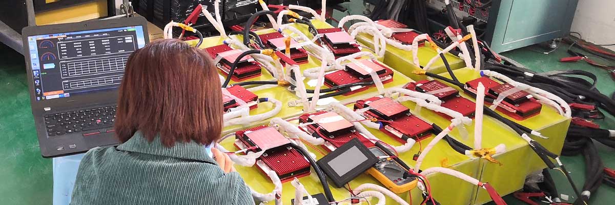
In our recent case, the deviation was “very small.” In a real-world scenario, that tiny amount of noise wouldn’t affect the product’s performance. However, accredited labs like SGS, Intertek, or TÜV operate on a binary Pass/Fail system.


A 1dB deviation over the limit is as much a “Fail” as a 50dB deviation. Once a failure is recorded, the lab requires:


A formal “Failure Analysis Report.”


Modified samples (Hardware changes).


A complete re-test of the failed parameters.


This “Domino Effect” eats away at your “Time-to-Market” (TTM), which is often the most valuable asset in the tech industry.


The “System-Level” Approach: Why Early Disclosure is Key

At our factory, we don’t just manufacture batteries; we engineer power systems. When you provide us with the exact list of certifications required for your target market at the start, we can adjust the following details before the first sample ever leaves our floor:


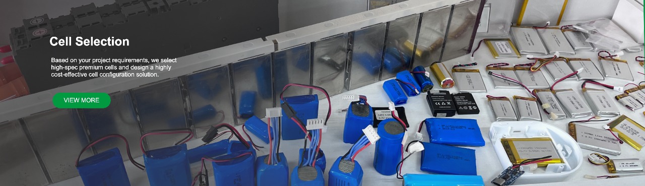
Charger Component Selection: We can opt for premium capacitors and inductors that naturally suppress EMI.


Shielding: We can add copper foil or specialized coatings to the internal housing of the charger or the battery casing.


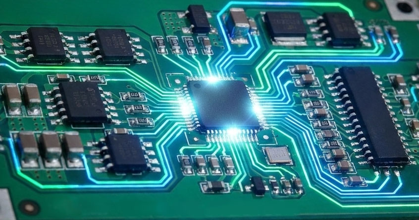
PCB Layout: Our engineers can optimize the trace routing on the protection board to minimize “antenna effects” that broadcast noise.


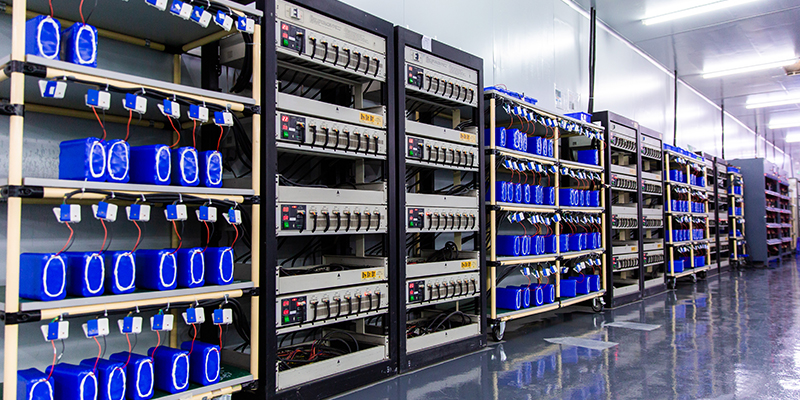
Pre-Testing: We can perform in-house “pre-compliance” scans to ensure the 99% success rate when the units hit the official SGS lab.


A Checklist for Global Battery Procurement

To ensure your next project moves from “Prototype” to “Market” without friction, we recommend following this technical checklist when requesting a quote:


List Every Target Market: Are you selling in the EU (CE), USA (UL/FCC), Japan (PSE), or Australia (RCM)? Each has different EMC and safety thresholds.


Define the Test Standard Early: Don’t just say “I need a certificate.” Specify if you need IEC 62133 (Safety), EN 55032 (EMC for Multimedia), or EN 60601 (Medical).


Specify the “System” Testing: Will the battery be tested inside your device, or as a standalone component with its charger? Lab results vary wildly depending on how the system is grounded.


Allow for “Engineering Margin”: Low-cost, “budget” chargers rarely leave any margin for EMC testing. If you need certification, be prepared to invest in a “Certified Grade” charger.

Conclusion: Partnership Over Procurement


The relationship between a buyer and a battery factory should not be a simple transaction; it should be a technical partnership. The recent EMC failure we experienced served as a powerful reminder that transparency in certification requirements is the best way to save money.


By informing us of your full regulatory roadmap—including the “small” details like CE/EMC requirements—you empower our engineering team to provide a solution that is “Ready for Lab” on day one. This proactive communication prevents wasted testing fees, protects your timeline, and ensures that your brand is associated with quality and compliance.


Are you planning a project that requires SGS or UL certification? Don’t leave your compliance to chance. Contact our technical sales team today. We provide professional guidance on cell selection, PCM engineering, and charger compatibility to ensure your product passes the first time, every time.


HIMAX ELECTRONICS — Powering Innovation with Precision.

Li-ion 4S2P battery

Introduction

Today, Himax Electronics officially launches its latest innovation — the Li-ion 4S2P 14.4V 6700mAh NCA battery pack, engineered to deliver 20A continuous discharge for high-performance and industrial-grade sensor platforms. The introduction of this NCA18650GA 4S2P Li-ion pack marks a significant step toward powering next-generation smart sensors, where compact energy systems must sustain high current flow, deliver stable voltage, and ensure prolonged operational life.

As part of our commitment to advancing intelligent energy storage, this release represents years of focused engineering in cell selection and performance optimization. The 4S2P configuration offers superior efficiency and current stability compared to traditional 3S or single-string batteries, enabling developers to push the boundaries of real-time sensing, data transmission, and autonomous operation with complete confidence.

Technical Specifications

Specification Value
Model Li-ion 4S2P (NCA18650GA)
Nominal Voltage 14.4V (16.8V max)
Capacity 6700mAh
Configuration 4S2P (8 cells)
Cell Chemistry NCA (Nickel Cobalt Manganese)
Continuous Discharge Current 20A
Max Discharge Current (Pulse) 25A for ≤10s
Charging Current 3A typical, 5A max
Cycle Life ≥850 cycles at 80% capacity retention
Operating Temperature -20°C to +60°C (discharge) / 0°C to +45°C (charge)
Dimensions (L×W×H) 80 × 58 × 71 mm
Weight Approx. 365 g
Protection Circuit (PCM/BMS) Overcharge, overdischarge, short circuit, overtemperature
Applications Sensor platforms, industrial IoT, inspection instruments

Breakthrough Performance for Next-Gen Sensor Platforms

The new 14.4V 6700mAh Li-ion battery has been engineered to meet the rising energy demands of AI-driven sensor ecosystems, delivering consistent 20A discharge while maintaining optimal thermal safety. Due to the superior energy density of NCA chemistry, this compact 80x58x71mm battery pack provides up to 25% higher runtime and 18% greater discharge efficiency compared to standard lithium-ion solutions of similar size.

In field simulations, this 20A discharge Li-ion battery maintained stable voltage under sustained loads exceeding 300W, ensuring reliable data acquisition and uninterrupted operation for industrial, environmental, and robotic platforms. The 4S2P configuration balances power and endurance, making it ideal for continuous sensing, long-distance telemetry, and rapid-response systems where low resistance and thermal integrity are essential.

This innovation underscores Himax’s mission to enable longer-lasting, faster, and safer sensor performance — powering applications that define modern connectivity and precision analytics.

Key Advantages & Industry Impact

  • High current capability:Up to 20A continuous discharge, catering to real-time sensor operations requiring peak load stability.
  • Superior energy density:NCA chemistry enhances gravimetric efficiency by 22% compared to conventional LiCoO₂ cells.
  • Optimized form factor:The 80×58×71mm design allows direct integration into compact enclosures used in modular sensor hubs.
  • Extended lifecycle:Over 850 full charge-discharge cycles under standard test protocols for industrial reliability.
  • Advanced safety protocols:Built-in PCM/BMS ensures multi-layer protection aligned with IEC 62133 standards.


Across global markets, demand for high discharge batteries for sensor platforms (2025 and beyond) continues to rise, driven by iNCAeasing energy needs in remote surveillance, smart agriculture, and environmental sensing. Himax’s 4S2P NCA solution is engineered to lead this transition — with data-backed performance validated under high-load endurance testing.

Comparison with Existing Sensor Power Solutions

Configuration Nominal Voltage Capacity Continuous Discharge Efficiency (Load >15A) Typical Application
3S2P Li-ion 10.8V 6700mAh 15A 78% Basic monitoring nodes
4S2P NCA Li-ion (Himax) 14.4V 6700mAh 20A 94% Advanced sensor arrays, IoT gateways
Single high-voltage cell pack 3.6V 3350mAh 10A 70% Lightweight, low-power systems

This performance leap positions the Himax 14.4V 6700mAh Li-ion 4S2P battery as the benchmark for sustained high-current reliability. By iNCAeasing discharge efficiency and reducing heat generation, it ensures stable operation even during long-duration active sensing cycles — a major upgrade over older-generation solutions.

Design & Integration Guidance for Engineers

14.4V 6700mAh Li-ion

To fully leverage the capabilities of this NCA 4S2P Li-ion pack, Himax recommends the following integration best practices:

  • Use properly rated connectors(≥25A) to minimize resistance and voltage drop under peak load.
  • Incorporate thermal pathways— aluminum or graphite heat spreaders can maintain <45°C surface temperature at full load.
  • Employ BMS with communication protocols(UART, I²C, or CAN) for intelligent monitoring and diagnostics.
  • Calibrate firmware voltage thresholdsto 16.8V charge and 12.0V cutoff for optimal longevity.
  • Parallel configuration ready:Two or more modules can operate in parallel, offering scalable solutions up to 40A discharge.


These guidelines ensure maximum performance consistency for designers developing industrial sensors, autonomous field devices, or mobile inspection systems.

Engineered Safety & Long-Term Reliability

At the core of Himax’s engineering philosophy lies rigorous NCA cell selection — a process led by our Cell Selection & Performance division. Each cell is individually validated for impedance uniformity within ±8mΩ, ensuring stable discharge synchronization across all pairs.

Integrated PCM and smart BMS technologies continuously monitor charge current, cell temperature, and voltage deviations, enabling proactive fault response. Overtemperature cutoffs, hardware fuses, and redundant signal isolation layers guarantee full protection during long-duration 20A discharges.

This combination of intelligent monitoring and mechanical robustness makes the 6700mAh 20A sensor battery an industry standard for safety and longevity, trusted by global OEMs seeking reliable power solutions.

4S2P 14.4V 6700mAh battery

FAQ

  1. How long does the 20A discharge run time last?
    Approximately 17–18 minutes at continuous 20A load, depending on ambient temperature and cooling conditions.
  2. Can this battery operate in outdoor environments?
    Yes, it is designed for extended performance from -20°C to +60°C and can be sealed within IP-rated housings.
  3. Is customization possible for different sensor platforms?
    Absolutely. Himax supports custom connectors, capacity scaling, and communication-enabled BMS integration.
  4. What makes this NCAbattery different from conventional Li-ion packs?
    Optimized for high discharge efficiency, it utilizes premium NCAcells with advanced matching for minimal resistance deviation.
  5. Can multiple packs be connected for extended runtime?
    Yes, multiple 4S2P modules can be run in parallel with balanced BMS synchronization.
  6. What is the recommended charging method?
    A 16.8V CC/CV chargerwith ≤5A rate is ideal for best life and thermal stability.
  7. How many cycles does it sustain under heavy use?
    Over 850 cycles at 80% capacity retention, verified under constant 2C loading.
  8. Which applications benefit most from this battery?
    Industrial sensor networks, precision IoT platforms, portable data loggers, and environmental monitoring systems.

Conclusion

With the launch of the Li-ion 4S2P 14.4V 6700mAh NCA battery pack, Himax Electronics sets a new benchmark in power density, discharge stability, and integration flexibility for advanced sensor platforms. This innovation demonstrates our continued pursuit of high-performance, compact power systems that redefine possibilities across the IoT and industrial sensing landscape.

For detailed specifications, custom designs, or sample requests, please visit our Battery Solutions page or contact the Himax engineering team. Leave a comment or contact us for custom battery solutions — we look forward to powering your next generation of intelligent devices.

Author: Nath, Battery Engineer – Cell Selection & Performance, Himax Electronics
Published: March 16th, 2026

26650 9.6V 3Ah battery

In the battery industry, transparency is often a double-edged sword. On the surface, two battery packs might look identical on a datasheet: 11.1V, 3000mAh, Li-ion. However, one quote comes in at $9, while another is $13.


If the capacity and voltage are the same, why the massive price gap? The answer usually lies in what’s happening inside the shrink wrap.


The Anatomy of a Price Difference: A Real-World Example

We recently consulted for a client requiring an 11.1V 3000mAh pack for a high-drain application needing a 10A continuous discharge.


The “Low-Cost” Quote: Used standard Chinese-brand cells designed for low-drain electronics.


Our Solution: We utilized Samsung 30Q (5C high-rate) cells paired with a custom-engineered PCM (Protection Circuit Module) capable of handling sustained high currents without overheating.


The “cheaper” battery wasn’t just a bargain—it was a technical failure waiting to happen. Using a low-rate cell for a 10A application leads to voltage sag, excessive heat, and a drastically shortened cycle life.

  Factors That Actually Drive Battery Costs

  1. Cell Origin and Discharge Rate (C-Rating)

Not all 3000mAh cells are created equal. A “Tier 1” cell (like Samsung, LG, or Panasonic/Sanyo) offers consistency and safety that budget cells cannot match. More importantly, high-discharge cells (5C, 10C, or higher) require more sophisticated internal chemistry and materials, which naturally increases the cost compared to standard cells used in low-power devices like flashlights.


  1. The PCM/BMS: The Brain of the Battery

A cheap protection board might only offer basic overcharge protection. A professional-grade, custom PCM ensures the battery can handle specific peak currents, manages thermal dissipation, and prevents the pack from shutting down prematurely under load. Cutting costs here is the leading cause of “dead on arrival” products in the field.


  1. True Testing vs. Paper Specs

Low-cost suppliers often quote “theoretical” capacities. A professional factory tests every batch under real-world load conditions to ensure that if we promise 10A, the battery delivers 10A safely until the end of the discharge cycle.


Why “Cheap” Is Often More Expensive

Choosing a supplier based solely on the lowest quote often leads to a “hidden” tax:


Wasted R&D Time: Testing a low-quality sample only to have it fail during your pilot phase.


Reputational Damage: If a battery fails in your customer’s hands, the cost of a recall or a bad review far outweighs the several dollars saved per unit.


Shipping & Lab Costs: Repeatedly shipping samples for re-testing is a drain on both your budget and your project timeline.


Our Advice: Be Specific to Stay Competitive

To get the most accurate and competitive quote, we recommend being as transparent as possible with your supplier from Day 1:

Define your Continuous and Peak Discharge Current.


Specify if you have a brand preference for cells (or if you are open to high-quality domestic alternatives).


Outline your operating environment (Temperature, vibration, etc.).


At HIMAX, we don’t just sell batteries; we provide power insurance. By confirming your exact specifications upfront, we ensure that the first sample you test is the only sample you’ll need to approve.

In an increasingly connected world, reliable power is non-negotiable. But what happens when “reliable” needs to withstand conditions that would bring standard batteries to their knees? From scorching desert sun to engine compartments operating at peak temperatures, many critical applications demand power solutions that are not just robust, but genuinely heat-resistant. At HIMAX, we understand these challenges intimately. That’s why we’re proud to introduce our specialized High-Temperature LiPo Battery (3.7V, 500mAh, 6C Discharge), meticulously engineered to thrive where conventional batteries fail.


The Unseen Threat: Why Temperature Matters for Batteries


Lithium Polymer (LiPo) batteries are ubiquitous due to their high energy density and flexible form factors. However, they are also inherently sensitive to temperature extremes.


Heat Acceleration: Elevated temperatures accelerate internal chemical reactions, leading to faster degradation, reduced cycle life, and, in severe cases, thermal runaway—a dangerous and irreversible overheating event.


Cold Compromise: While this article focuses on heat, it’s worth noting that extremely low temperatures can also hinder battery performance, causing increased internal resistance and reduced usable capacity.


Designing a battery for extreme temperatures isn’t just about tweaking existing chemistries; it’s a holistic engineering challenge that demands advanced materials, precise manufacturing, and rigorous testing.

LiPO-US-NI-MH

Our Solution: The 602735 High-Temperature LiPo Powerhouse


We’ve developed a specific LiPo cell, the 602735 (6mm thickness, 27mm width, 35mm length cell), which forms the core of our high-temperature solution. This 3.7V, 500mAh battery pack, with overall dimensions of 6x27x38mm, is far more than just a compact power source; it’s a testament to specialized engineering.


Key Specifications at a Glance:

Nominal Voltage: 3.7V

Capacity: 500mAh

Cell Size: 602735

Pack Dimensions: 6mm (Thickness) * 27mm (Width) * 38mm (Length)

Discharge Rate: 6C (Capable of delivering 3000mA continuously)

Charge Rate: 1C (Standard charging at 500mA)

Operating Temperature (Discharge): -20°C to +85°C

Operating Temperature (Charge): +10°C to +85°C

Minimum Order Quantity (MOQ): 5,000 units

Sample Availability: 10 units for testing


Engineered for Endurance: How We Achieve 85°C Operation

Achieving a stable operating temperature range up to an astonishing 85°C is no trivial feat. It’s the culmination of several critical design and manufacturing choices:


Advanced Electrolyte Formulation: The secret sauce for high-temperature performance often lies in the electrolyte. We utilize a proprietary electrolyte blend that maintains its ionic conductivity and chemical stability even at elevated temperatures, resisting decomposition that plagues standard electrolytes.


Robust Separator Material: The separator is a crucial component that prevents the anode and cathode from short-circuiting. Our high-temperature LiPo batteries employ specialized polymer separators with exceptional thermal stability, preventing shrinkage or melting at extreme temperatures.


Enhanced Electrode Materials: Both the cathode and anode materials are selected and treated to minimize degradation and maintain structural integrity under thermal stress, ensuring consistent performance and longevity.


Optimized Cell Structure: Every aspect of the cell’s internal structure is optimized for thermal management. This includes the stacking process, the quality of the current collectors, and the precision of the sealing, all contributing to efficient heat dissipation and containment.


Rigorous Testing Protocols: Beyond standard capacity and cycle life tests, our high-temperature batteries undergo specific environmental testing in thermal chambers, simulating real-world conditions from extreme cold to prolonged heat exposure to validate their performance and safety at 85°C.


Where Reliability Meets Extremes: Ideal Applications

The demanding specifications of our high-temperature LiPo battery make it perfectly suited for mission-critical applications where failure is not an option and environmental conditions are harsh.


  1. Outdoor Surveillance and Security Systems

Imagine security cameras deployed in remote locations, exposed to direct sunlight in summer or integrated into heated enclosures. These systems require continuous power, often with periodic bursts for data transmission or night vision. Our 85°C battery ensures uninterrupted operation, reducing maintenance calls and enhancing security reliability.


  1. Automotive and Emergency Vehicle Electronics

Police Cars, Ambulances, Fire Trucks: These vehicles are packed with sensitive electronics, from GPS and communication systems to dashcams and diagnostic tools. The interior and engine bay environments can reach extreme temperatures. Our battery can reliably power auxiliary devices, LED warning lights, and data recorders, operating flawlessly amidst engine heat and variable external conditions.


Fleet Management & Telematics: For commercial fleets, devices tracking location, driver behavior, and cargo status must function consistently. Our high-temp LiPo ensures these critical telematics units remain powered, regardless of the vehicle’s operational temperature.


  1. Industrial Monitoring & IoT Devices

From oil and gas pipelines in the desert to manufacturing facilities with high ambient temperatures, industrial IoT sensors and monitoring equipment need dependable power. Our battery can power sensors for predictive maintenance, environmental monitoring, or asset tracking, offering a long service life in challenging industrial settings.


  1. Specialized Aerospace and Defense Applications

While specific applications are often proprietary, any unmanned aerial vehicle (UAV), ground sensor, or portable equipment used in high-altitude or high-temperature defense scenarios can benefit from a power source designed for such extremes.

UAV LiPo battery 5000mAh

The HIMAX Advantage: Beyond the Specs


Choosing HIMAX means partnering with a factory that prioritizes engineering excellence and application-specific solutions.


Dedicated R&D: Our investment in materials science and cell chemistry ensures we stay at the forefront of battery technology, especially for niche requirements like high-temperature performance.


Scalable Production: With an MOQ of 5,000 units, we are equipped to support significant projects while maintaining the highest quality control standards.


Commitment to Quality: Every batch undergoes rigorous testing to meet our stringent performance and safety benchmarks.


Sample Confidence: We offer 10 samples for testing to allow you to validate our battery’s performance in your specific application environment with complete confidence before committing to mass production.


Ready to Power Your Extreme Environment Application?


Don’t let environmental challenges compromise your product’s performance or reliability. Our 3.7V 500mAh High-Temperature LiPo battery is designed to deliver consistent, dependable power when it matters most, allowing your innovations to operate flawlessly in the toughest conditions.


Contact our sales team today to discuss your project requirements and request your sample batch. Let us help you master the heat.

4s-bms

Modern lithium battery systems rely heavily on communication interfaces to monitor status, ensure safety, and exchange data with host devices. A Battery Management System (BMS) acts as the “brain” of a lithium battery pack, and communication protocols are the language it uses to talk with chargers, controllers, computers, and user interfaces.


This article explains RS232, RS485, I²C, and SMBus communication protocols and how each is commonly applied in lithium battery BMS systems.

1.RS232 Communication

What is RS232?

RS232 is one of the oldest and simplest serial communication standards. It is a point-to-point, single-ended communication method that transmits data using voltage levels.

Key characteristics:


  • Point-to-point communication (one device to one device)
  • Short communication distance (typically <15 meters)
  • Relatively low noise immunity
  • Simple wiring (TX, RX, GND)
  • Baud rates typically up to 115200 bps


RS232 in Lithium Battery BMS

In lithium battery applications, RS232 is mainly used for:


  • BMS configuration and debugging
  • Factory testing
  • PC-to-BMS communication via USB-to-RS232 adapters


Typical data exchanged:


  • Cell voltages
  • Pack voltage and current
  • State of Charge (SOC)
  • Temperature readings
  • Fault and protection status
  • Parameter configuration (over-voltage, over-current, etc.)


Advantages for BMS:


  • Easy to implement
  • Widely supported by BMS tools
  • Low cost


Limitations:


  • Not suitable for long distances
  • Poor resistance to electrical noise
  • Not ideal for industrial or automotive environments


2. RS485 Communication

What is RS485?

RS485 is a differential serial communication standard designed for robust, long-distance, and multi-device communication.


Key characteristics:

  • Differential signaling (A/B lines)
  • Communication distance up to 1200 meters
  • High noise immunity
  • Supports multiple devices on the same bus
  • Often used with Modbus protocol


RS485 in Lithium Battery BMS

RS485 is widely used in industrial, energy storage, and electric vehicle applications.

Common BMS applications:


  • Communication between BMS and inverter
  • Battery rack or module networking
  • Energy storage systems (ESS)
  • Robotics and industrial equipment


Typical data exchanged:


  • Real-tme battery status
  • Alarm and fault information
  • Charge/discharge limits
  • SOC / SOH data


Advantages for BMS:


  • Long cable distance
  • Excellent noise resistance
  • Supports multi-battery systems
  • Stable in harsh environments


Limitations:

  • More complex than RS232
  • Requires proper termination and addressing


3. I²C Communication


What is I²C?

I²C (Inter-Integrated Circuit) is a short-distance, low-speed communication protocol designed for communication between chips on the same PCB.


Key characteristics:

  • Two-wire interface (SDA, SCL)
  • Master-slave architecture
  • Short distance (usually <1 meter)
  • Low power consumption


I²C in Lithium Battery BMS

I²C is mostly used inside the battery pack, rather than for external communication.

Common BMS applications:


Communication between BMS MCU and:

  • Cell monitoring ICs
  • Temperature sensors
  • EEPROM / memory chips
  • Internal data acquisition and control


Advantages for BMS:

  • Simple wiring
  • Low power consumption
  • Ideal for internal electronics


Limitations:

  • Not suitable for long distances
  • Sensitive to noise
  • Not designed for external system communication


4. SMBus Communication


What is SMBus?

SMBus (System Management Bus) is a derivative of I²C, specifically designed for power and battery management applications.


Key characteristics:

  • Based on I²C physical layer
  • Defined timing and voltage levels
  • Standardized command set
  • Supports battery management functions

SMBus in Lithium Battery BMS

SMBus is widely used in smart battery systems, especially for consumer electronics and industrial devices.


Common applications:

  • Laptop batteries
  • Medical devices
  • Smart battery packs
  • Communication between battery and host system


Typical data exchanged:

  • Remaining capacity
  • Full charge capacity
  • Cycle count
  • Battery health (SOH)
  • Charging status
  • Manufacturer data

Advantages for BMS:

  • Industry-standard smart battery protocol
  • Plug-and-play compatibility
  • Rich battery information support


Limitations:

  • Limited communication distance
  • Requires host support for SMBus
  • Less flexible than custom protocols


5. Comparison Summary

Protocol Distance Noise Immunity Typical Use in BMS
RS232 Short Low BMS setup, debugging, PC tools
RS485 Long High ESS, inverters, industrial systems
I²C Very short Low Internal BMS IC communication
SMBus Short Medium Smart batteries, host communication

Protection-functions-of-the-BMS


6. Choosing the Right Communication for a BMS

The choice of communication protocol depends on:

  • Application environment(consumer vs industrial)
  • Communication distance
  • System complexity
  • Host device compatibility
  • Noise and EMI conditions


Many modern lithium battery systems use multiple protocols simultaneously, for example:

  • I²C internally inside the BMS
  • RS485 to communicate with an inverter
  • RS232 or USB for configuration and service
  • SMBus for smart battery applications


Conclusion

RS232, RS485, I²C, and SMBus each play a distinct role in lithium battery BMS communication. Understanding their differences helps system designers and users select the most suitable interface for reliable monitoring, control, and safety.

As lithium battery applications continue to expand in energy storage, robotics, and electric mobility, choosing the right communication protocol is essential for performance, safety, and system integration.


bms architecture

Below is a clear, BMS-focused explanation of how many data cables (signal wires) each communication protocol requires, plus what’s usually added in real battery systems.


1. RS232


Data cables required

2–3 signal wires

Signal Purpose
TX Transmit data
RX Receive data
GND Signal ground (required)

Typical wiring

  • Minimum:TX + RX + GND → 3 wires
  • Sometimes additional handshake lines (RTS/CTS), but rarely used in BMS


In lithium BMS

  • Usually 3 wires total
  • Common for PC ↔ BMS configuration
  • Often exposed as a 4-pin or 5-pin connector, but only 3 are active

battery-intelligent-bms

2. RS485

Data cables required

2 signal wires (+ optional ground)

Signal Purpose
A (D+) Differential data
B (D−) Differential data
GND Reference ground (optional but recommended)

Typical wiring

  • Minimum:A + B → 2 wires
  • Recommended:A + B + GND → 3 wires


In lithium BMS

  • Most industrial BMS use 2-wire half-duplex RS485
  • Shielded twisted pair is strongly recommended
  • Ground improves stability in noisy environments


3. I²C

Data cables required

2 signal wires (+ power & ground)

Signal Purpose
SDA Data line
SCL Clock line
GND Ground
VCC Power (often shared)

Typical wiring

  • Data only:SDA + SCL → 2 wires
  • Actual connection:SDA + SCL + GND (+ VCC) → 3–4 wires


In lithium BMS

  • Used inside the battery pack
  • Very short distance (PCB or short harness)
  • Always shares ground and power internally


4. SMBus

Data cables required

2 signal wires (+ power & ground)
(Same physical wiring as I²C)

Signal Purpose
SDA Data
SCL Clock
GND Ground
VCC Power

Typical wiring

  • Data only:SDA + SCL → 2 wires
  • Actual system:SDA + SCL + GND (+ VCC) → 3–4 wires


In lithium BMS

  • Common in smart battery packs
  • Connects battery to host system (PC, laptop, medical device)
  • Often standardized 4-wire connector

5. Quick Comparison Table

Protocol Data Lines Only Typical Total Wires in BMS
RS232 2 (TX, RX) 3 (TX, RX, GND)
RS485 2 (A, B) 2–3 (A, B, GND)
I²C 2 (SDA, SCL) 3–4 (SDA, SCL, GND, VCC)
SMBus 2 (SDA, SCL) 3–4 (SDA, SCL, GND, VCC)


6. Practical BMS Notes (Very Important)


Ground is critical
Even if a protocol says “2 wires”, most real BMS systems are more stable with a shared ground.


RS485 ≠ RS232 wiring
Connecting RS232 directly to RS485 will damage communication (and sometimes hardware).


Cable type matters

RS485 → twisted pair, shielded

I²C / SMBus → short, clean, low-noise

RS232 → short cables only


Connector pin count ≠ data wire count
A “6-pin communication port” often uses only 2–3 signal lines.


Lithium-ion batteries have become the standard power source for everything from consumer electronics to electric vehicles, thanks to their high energy density, long cycle life, and relatively low self-discharge. However, their unique electrochemical characteristics make proper charging crucial. One of the most important rules in lithium-ion battery charging is that the charging current should not exceed 1C, which is the battery’s nominal capacity per hour. Exceeding this limit can compromise both safety and longevity.


1. Electrochemical and Thermal Reasons

Lithium-ion batteries store energy by moving lithium ions between the cathode and anode. During charging, lithium ions migrate from the cathode to intercalate into the graphite anode. When the charging current is too high:


-The lithium ions move too quickly, leading to lithium plating on the anode surface.

-Lithium plating can form dendrites that pierce the separator, potentially causing internal short circuits.

-High current also generates more resistive heat (I²R heating), which can raise the battery temperature and increase the risk of thermal runaway.


In short, excessive current increases both immediate safety risks and long-term structural damage inside the battery.

2. Impact on Battery Life


Charging with high current has a direct effect on the cycle life of lithium-ion batteries:


Accelerated degradation: Fast charging stresses the electrode materials, breaking down their microstructure and reducing capacity over time.


Reduced cycle count: For example, a typical lithium-ion battery charged at 1C might last 500 full cycles, while charging at 2C or 3C can reduce the cycle life to 200–300 cycles.


Electrolyte breakdown: High current can cause localized overheating and chemical reactions that degrade the electrolyte, further shortening battery life.


Thus, limiting the charging current helps maintain the battery’s long-term health and usable capacity.

3. Safety and BMS Considerations

High charging currents require precise monitoring and control:


Battery Management Systems (BMS) must track individual cell voltage, temperature, and current.


Exceeding 1C increases BMS complexity and the risk of mismanagement, which could lead to overheating or overvoltage conditions.


Large-capacity batteries, such as those used in electric vehicles, generally adopt 1C as the safe standard. Charging faster than 1C usually requires specialized high-power battery designs and enhanced thermal management systems.


4. Practical Guidelines


For consumer electronics, 0.5C–1C charging is standard and safe.


For industrial or large-format batteries, 1C is often used as a maximum safe charging rate, balancing speed and longevity.


Rapid charging beyond 1C is only recommended for batteries designed for high-power applications, with appropriate cooling and safety systems.


10C_discharge_battery

Conclusion

Charging current is not just a matter of convenience—it directly impacts safety, performance, and battery lifespan. Exceeding 1C can lead to lithium plating, overheating, reduced cycle life, and even catastrophic failure. Therefore, keeping the charging current at or below 1C is the best practice, providing an optimal balance between charging speed, safety, and battery longevity.

By understanding and following these guidelines, manufacturers, engineers, and users can ensure that li-ion batteries remain reliable, safe, and long-lasting.


Lithium-ion batteries have become ubiquitous in modern electronics due to their high energy density and long cycle life. However, their unique chemical characteristics make proper charging crucial for both safety and longevity. Among all charging methods, the CC/CV (Constant Current / Constant Voltage) method is universally recommended.


1. Chemical Characteristics of Lithium Batteries

Lithium batteries store energy by lithium ions intercalating/de-intercalating between the anode and cathode. Key characteristics:


Nonlinear voltage-SOC relationship: At the beginning and end of discharge, voltage changes quickly, while in the middle it’s relatively flat.


Sensitive to overvoltage: Exceeding 4.2V/cell (for typical LiCoO₂ batteries) can cause electrolyte decomposition, gas generation, or even thermal runaway.


Sensitive to overcurrent: High current accelerates electrode degradation and may even trigger internal short circuits.


Hence, charging must control both current and voltage.

custom lithium battery

2. CC/CV Charging Process


CC/CV charging splits the process into two stages:


① Constant Current (CC) Stage

Initial stage: battery voltage is low.

Charger provides a fixed current (e.g., 1C).

Battery voltage gradually rises to the target voltage (usually 4.2V/cell).

Purpose: Quickly charge the battery to ~70–80% capacity while keeping current safe to prevent overheating.


② Constant Voltage (CV) Stage

When battery voltage reaches 4.2V/cell (or rated voltage),

Charger maintains constant voltage, and the current gradually decreases.

Charging ends when current drops to a small value (e.g., 0.02C).

Purpose: Safely top off the battery and prevent overcharging.


3. Why You Can’t Use Only CC or CV

Charging Method Drawback
Constant Current only When battery voltage is near full, current doesn’t decrease → overcharge → electrolyte decomposition, gas, swelling, lifespan loss, or even fire.
Constant Voltage only When battery voltage is low, current is too high → overheating → battery damage, slow and unstable charging.

Therefore, CC/CV is the standard and safe charging method for lithium batteries: fast in CC stage, safe in CV stage.


4. Additional Notes

Charging current is usually 0.5C–1C; too high can damage the battery.


Charging at high or low temperatures affects efficiency and safety.


Using a smart BMS (Battery Management System) prevents overcharge or over-discharge.


CC/CV charging perfectly matches lithium battery chemistry: constant current charges fast, constant voltage finishes safely, ensuring safety, efficiency, and long life. It is the only recommended charging method for lithium batteries.


In conclusion, the CC/CV charging method is not arbitrary—it aligns perfectly with the chemistry of lithium-ion batteries. By charging with constant current initially and switching to constant voltage for finishing, it ensures that batteries are charged quickly, safely, and with minimal wear, making it the only recommended method for lithium-ion battery charging.


lifepo4-battery-cccv


48v-lithium-golf-cart-battery

In today’s battery technology landscape, lithium-ion batteries (NMC/NCA) and lithium iron phosphate (LiFePO4 or LFP) batteries are the two dominant chemistries. Together, they power the global transition to clean energy—supporting applications ranging from electric vehicles and consumer electronics to home energy storage and telecom backup systems.

Although both belong to the lithium family, their chemical structures lead to very different performance characteristics. Understanding these differences is essential for engineers, system integrators, and buyers who want to choose the most suitable battery solution for their application.

This article provides a clear, practical comparison to help you make an informed decision.

1. Chemical Fundamentals: Where the Differences Begin

The most fundamental difference between lithium-ion and LiFePO4 batteries lies in the cathode material, which directly determines energy density, safety, lifespan, and cost.

Lithium-ion Batteries (NMC / NCA)

Lithium-ion batteries use lithium nickel manganese cobalt oxide (NMC) or lithium nickel cobalt aluminum oxide (NCA) as the cathode material.
Thanks to their high operating voltage and layered crystal structure, these batteries can store more energy in a smaller and lighter package.
22.2v 28ah lithium battery pack

LiFePO4 Batteries (LFP)

LiFePO4 batteries use lithium iron phosphate as the cathode.
Their stable olivine crystal structure provides excellent thermal stability and strong resistance to degradation, which is the foundation of their long cycle life and high safety level.

2. Five Key Performance Dimensions Compared

Below is a simplified comparison across five critical performance areas that matter most in real-world applications.

1) Energy Density

Lithium-ion: High (200–300 Wh/kg)

LiFePO4: Medium (140–180 Wh/kg)

Selection insight:
If your product requires lightweight design or long runtime—such as electric vehicles, drones, or portable electronics—lithium-ion batteries are usually the better choice.
If size and weight are less critical, LiFePO4 is often preferred for its other advantages.

2) Safety

Lithium-ion: Medium

LiFePO4: High

LiFePO4 batteries have excellent thermal stability and are much less prone to thermal runaway, even under conditions such as overcharging, short circuit, or mechanical damage.
For applications where safety is the top priority, LiFePO4 is widely regarded as an inherently safer chemistry.

3) Cycle Life

Lithium-ion: 500–1,000 cycles

LiFePO4: 2,000–5,000 cycles (or more)

Selection insight:
For applications sensitive to total lifetime cost—such as energy storage systems, commercial vehicles, or backup power—LiFePO4’s long cycle life provides a clear advantage.

4) Cost

Lithium-ion: Higher (contains cobalt and nickel)

LiFePO4: Lower (iron and phosphate are abundant)

Raw material cost and price volatility make lithium-ion batteries more expensive.
LiFePO4 batteries benefit from lower and more stable material costs, which is a key reason for their rapid adoption in large-scale commercial and energy storage projects.

5) Low-Temperature Performance

Lithium-ion: Better

About 70% capacity retention at –20°C

LiFePO4: Weaker

About 50–60% capacity retention at –20°C

Selection insight:
For cold climates or outdoor applications, lithium-ion batteries perform better.
LiFePO4 systems can still be used in cold environments, but they often require heating elements or advanced thermal management.

3. Strengths and Challenges in Detail

Advantages and Challenges of Lithium-ion Batteries

Key advantages:

High energy density enables longer driving range or smaller battery packs

Supports fast charging and high power output

Ideal for performance-focused applications

Main challenges:

More sensitive to overcharging and high temperatures

Requires a precise and reliable battery management system (BMS)

Shorter cycle life compared to LiFePO4

Higher and less stable raw material costs

Advantages and Limitations of LiFePO4 Batteries

Key advantages:

Outstanding safety and thermal stability

Very long cycle life, reducing cost per kWh over time

No cobalt or nickel, making it more environmentally friendly

Stable performance over many years of use

Main limitations:

Lower energy density

Larger and heavier packs for the same capacity

Reduced performance in low-temperature environments

4. Application Scenarios: Which Battery Should You Choose?

Choose Lithium-ion If Your Priority Is:

Maximum energy density

Long-range electric vehicles

Drones and aviation-related systems

High-end consumer electronics

High power output

Power tools

Performance hybrid or electric vehicles

Cold climate operation

Outdoor or automotive applications in low temperatures

Choose LiFePO4 If Your Priority Is:

Safety and long-term reliability

Energy storage systems (ESS)

Solar storage

Telecom base station backup power

Lower total cost of ownership

Commercial EVs

Electric buses and logistics vehicles

Shared mobility fleets

Fixed installations with high safety requirements

Home energy storage

Security and monitoring equipment

Marine and UPS backup systems
lithium-ion-battery-charger

5. Future Trends: Competition or Coexistence?

The market is not moving toward a “winner-takes-all” solution. Instead, it is evolving toward application-based optimization.

Technology Evolution

Lithium-ion batteries are shifting toward high-nickel, low-cobalt formulations to increase energy density while reducing cost.

LiFeO4 batteries are improving pack-level efficiency through innovations such as CTP (Cell-to-Pack) and blade battery designs, which significantly increase volumetric energy density.

Mixed Battery Strategies

Some automakers now adopt dual chemistry strategies:

Entry-level models use LiFePO4 for cost and safety

Premium models use lithium-ion for performance and range

System-Level Optimization

Regardless of chemistry, system design is critical.
Battery performance and safety heavily depend on:

Battery management system (BMS)

Thermal management design

Manufacturing quality and consistency

In many cases, a well-designed LiFePO4 system can outperform a poorly designed lithium-ion system—and vice versa.

Conclusion: There Is No Perfect Battery, Only the Right One

The choice between lithium-ion and LiFePO4 batteries is ultimately a strategic trade-off between energy density and safety/longevity.

If every gram and every kilometer matters, lithium-ion is often the right answer.

If long term stability, safety, and life cycle cost are more important, LiFePO4 is the smarter choice.

There is no universal “best battery”—only the most suitable solution for a specific application.

When selecting a battery, always return to the core question:
Do you need maximum performance today, or stable and reliable operation for the next ten years?
The answer will guide you to the right technology.


3.7V-18650-battery-cell

In the world of cylindrical lithium-ion batteries, 18650 and 26650 are two of the most well-known and widely used formats. They have been on the market for many years and are still essential in many industries today.

The numbers in their names act like an “ID card”:

The first two digits indicate the diameter (in millimeters)

The next two digits indicate the length (in millimeters)

The final “0” means the battery is cylindrical

For example:

18650 = 18 mm diameter, 65 mm length

26650 = 26 mm diameter, 65 mm length

Although they share the same length, the 8 mm difference in diameter leads to clear differences in capacity, performance, cost, and application. Understanding these differences is a key step in designing efficient and reliable battery-powered products.
26650 lifepo4 battery and Li Ion Customized Battery Manufacturing

1. Key Differences: More Than Just Size

The table below highlights the main differences between 18650 and 26650 lithium-ion batteries.

Physical Size

18650:

Diameter: 18 mm

Length: 65 mm

26650:

Diameter: 26 mm

Length: 65 mm

Both batteries have the same height, but the larger diameter of the 26650 gives it more internal volume and higher weight, which directly affects capacity.

Typical Capacity

18650:

Common range: 1,800 mAh – 3,500 mAh

26650:

Common range: 4,500 mAh – 5,000 mAh

Under the same battery chemistry, a 26650 cell usually offers more than 50% higher capacity than an 18650 cell, simply because it is larger.

Energy Density

18650: Higher energy density

26650: Lower energy density (compared to 18650)

The 18650 format has been produced on a massive scale for many years. Its manufacturing process is extremely mature and highly standardized, which allows it to achieve better energy density per unit volume.

Discharge Performance

18650:

Very wide range

From standard cells (around 3C) to high-power cells (10C or higher)

26650:

Usually moderate discharge rates

Most models focus on 1C–3C continuous discharge

The 18650 market offers more high-rate power cells, making it suitable for applications that require strong current output.
The 26650 focuses more on a balance between capacity and stable continuous discharge.

Cost and Market Availability

18650:

Lower cost

Extremely widely available

Many brands and suppliers

26650:

Higher cost per cell

Fewer manufacturers and options

The 18650 is an industry-standard cell. Large-scale production creates strong cost advantages.
In comparison, the 26650 supply chain is smaller, which affects both price and availability.

Typical Applications

18650 batteries are commonly used in:

Laptops

Power tools

High-end flashlights

Drones

Electric bicycles and scooters

26650 batteries are commonly used in:

Solar street lights

Energy storage systems

UPS systems

Telecom backup power

Large lighting equipment

In simple terms:

18650 = flexibility and performance

26650 = capacity and durability

2. Shared Advantages: Why They Remain Popular

Despite their differences, both 18650 and 26650 batteries share the core advantages of high-quality cylindrical lithium-ion cells:

High energy density compared with NiMH or lead-acid batteries

Long cycle life, often more than 500 cycles to 80% capacity

No memory effect, allowing flexible charging

Stable nominal voltage (typically 3.6V–3.7V)

Easy pack assembly, as cylindrical cells are easy to connect in series and parallel using holders or brackets

These advantages make them reliable building blocks for battery packs of many sizes and voltage levels.

3. Inherent Limitations: What System Design Must Address

Both formats also share some limitations that designers must consider:

Fixed shape
Cylindrical cells cannot fully use irregular internal space, unlike pouch batteries

Protection required
A protection circuit or battery management system (BMS) is essential to prevent overcharge, over-discharge, over current and short circuits.

Safety design challenges
In extreme thermal runaway cases, cylindrical metal shells may vent gas. Proper pack-level thermal design and safety spacing are important.

These issues do not prevent their use, but they must be addressed through good system-level design.

4. How to Choose: A Practical Decision Guide

Choosing between 18650 and 26650 is mainly about matching the battery to your core requirements.

Step 1: Space and Energy Requirements

If your product has limited space and needs high energy density, 18650 is usually the better choice.

If space allows a larger diameter and you want higher capacity per cell to reduce the number of parallel cells, 26650 is a strong option.

Step 2: Discharge Needs and Cost

For applications that require high current or high power, such as power tools or fast-moving drones, high-rate 18650 cells are recommended.

For applications that focus on medium-rate continuous discharge and long runtime, such as energy storage or lighting, 26650 cells often provide better value.

For cost-sensitive, high-volume projects, the mature 18650 supply chain usually offers more competitive pricing.

Application-Based Summary

Choose 18650 when designing:

Portable consumer electronics

Lightweight electric mobility products

Power tools or devices with high power demand

Choose 26650 when designing:

Energy storage systems

Long-runtime lighting solutions

Products with enough space and strict capacity requirements per cell
high-quality-18650-battery-holder-materials

Conclusion

18650 and 26650 batteries are not competitors, but complementary solutions.

The 18650 dominates portable and high-performance applications thanks to its excellent standardization, energy density, and cost advantages.

The 26650 holds a strong position in energy storage and long-runtime applications due to its higher single-cell capacity and durability.

When making a decision, move beyond the simple question of “which is better.”
Return to the basics of product design:

What are your space limits, energy needs, discharge requirements, and cost targets?

Once these questions are answered, the right battery format will become clear.